
![]()
![]()
![]()
![]()
![]()
![]()
![]()
![]()
Engineering Creativity for Neuroscience
BioStim Biological Stimulator System
• Sophisticated, top-grade physiological stimulators. They meet any difficult requirements of any physiological laboratories.
• Despite their powerful features, they are easy-to-use.
• Versatile equipments.
• Compatible with every PC-based data acquisition system.
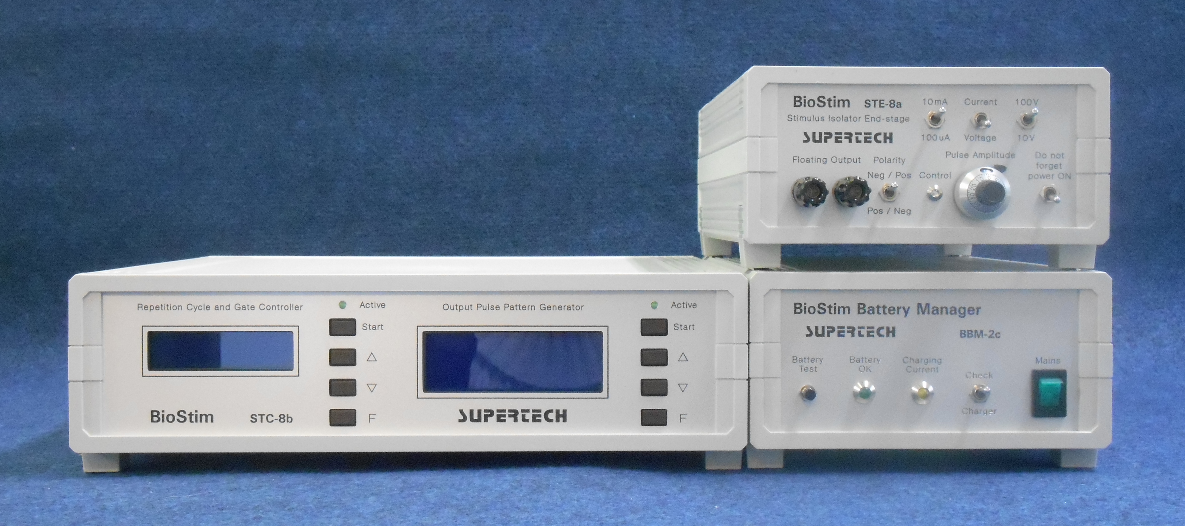
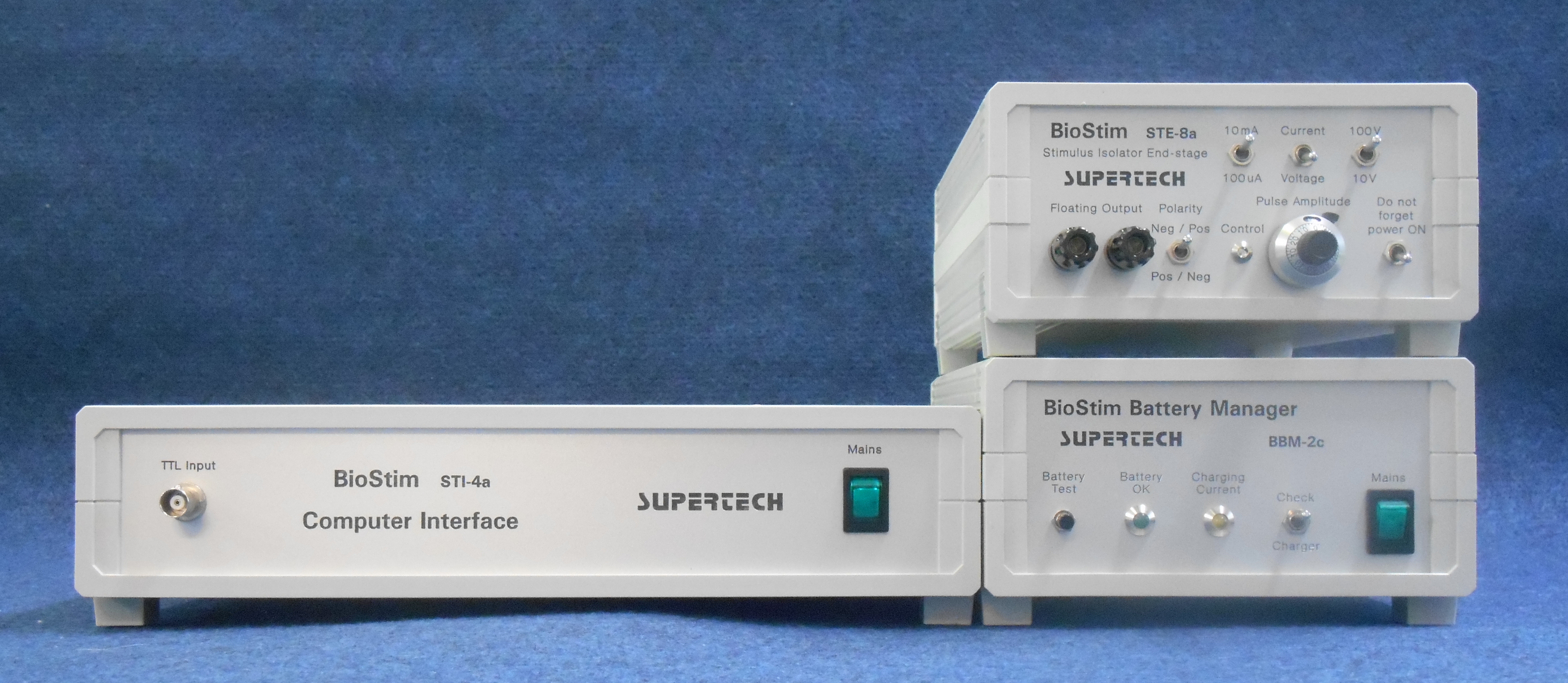 Stand-alone (left) and PC-controlled (right) stimulator system. Click on the picture to get it in full size
The Parts of the BioStim Biological Stimulator System
The parts of the BioStim system can be divided into two functional groups. The time parameters are generated by the fully digital BioStim Controller or by any 3rd-party pulse pattern generator. The analog constant voltage and/or constant current sources are implemented in the Stimulus Isolators (in other words stimulus isolators are End-stages). The Stimulus Isolator units can be used alone, because they have got standard TTL control inputs to receive the pulse sequences from any PC-based DAQ system or program package. The parts of the system are manufactured as independent equipments. On the one hand it results a more flexible and variable system, because the similar parts (e.g. the Stimulus Isolators) are compatible and they can be changed easily. On the other hand the divided system meets the special requirements much better. The Stimulus Isolators can be located close to the biological objects in the shielded environment, but the digital BioStim Controller and the high voltage Battery Manager can be placed anywhere else. BioStim Computer Interface is an alternate of the BioStim Controller in special cases. You can find detailed descriptions about each components of the BioStim system in the appropriate paragraphs below.
The general overview of the BioStim Universal Biological Stimulator System is downloadable.
Our method is, how we improve the features of our BioStim equipments, that we collect all the notices and feedbacks from our customers. We receive ideas of our customers and we implement their (may be your) knowledge into the features of BioStim.
The BioStim system must not be used in human experiments, because it has not got approval for human applications.
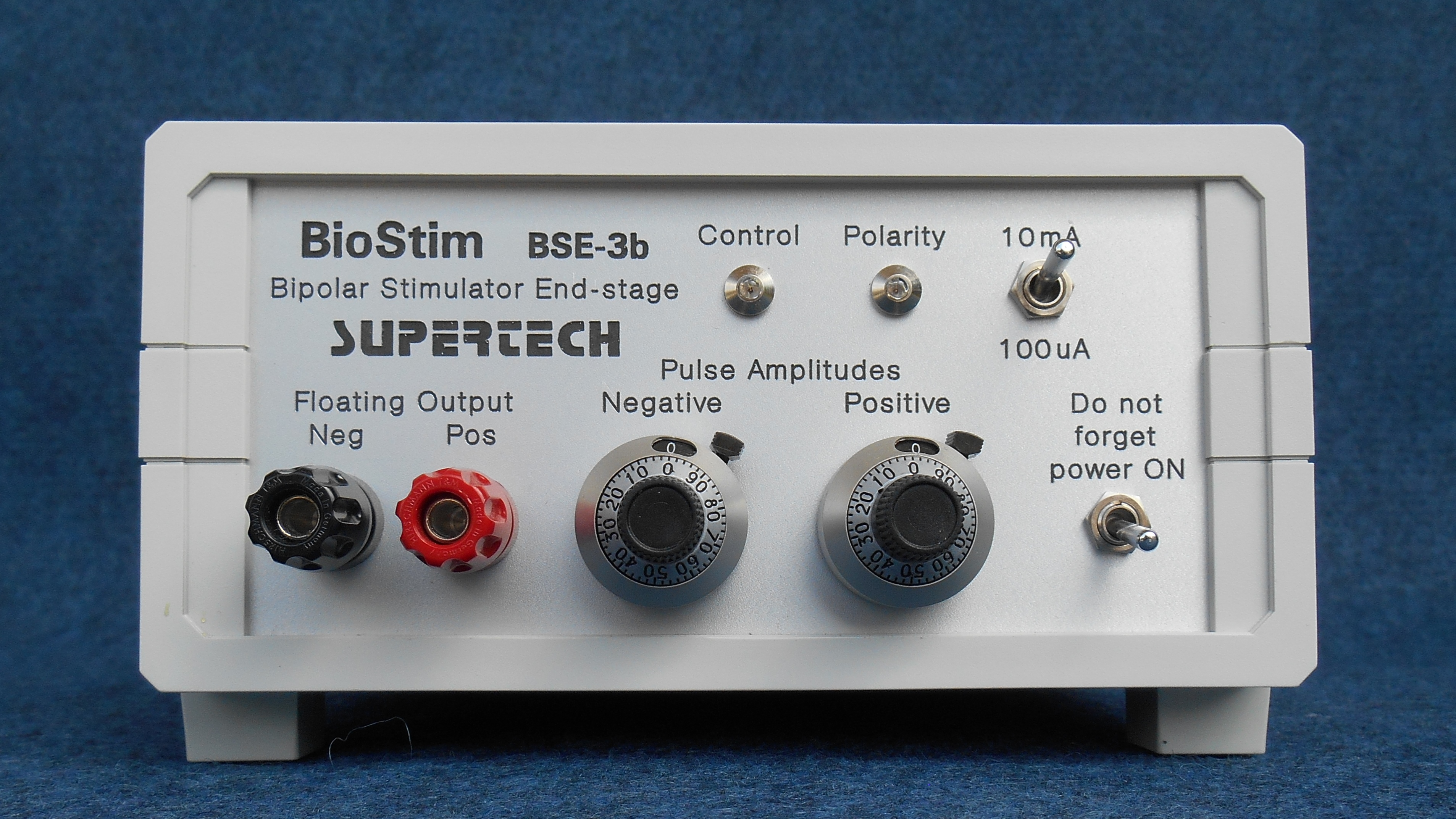
Bipolar Stimulus Isolator (with Rechargeable Battery) BSE-4x IMPROVED
Bipolar Battery-supplied Stimulus Isolator BSE-4x is one of the most sophisticated stimulus isolator constructions in the choice of Supertech Instruments. Its counterpart is the Monopolar Battery-supplied Stimulus Isolator for monopolar pulse output. The difference between the two versions is, that in the Monopolar Stimulus Isolator there are both a Constant Current generator and a Constant Voltage generator, as well. In the Bipolar Stimulus Isolator there is a Constant Current generator only, but a cumulative charge increase effect does not appear during its usage. Bipolar Stimulus Isolator is supplied from its built-in rechargeable battery pack. Our battery-supplied stimulus isolators are floating equipments. It means, that they have got negligible capacity to the mains or to the ground (> 10 pF).
We have improved the switching speed of this equipment to a high level. Please check the technical data below. If you have a slower older version, we can upgrade it for you on a reasonable price.
Bipolar Stimulus Isolator BSE-4x is a research grade stimulus isolator unit. There is a precision, bipolar constant current generator built into this Stimulus Isolator. It is optimized for biological measurements carried out on in-vivo subjects and on living animals. It has been designed for the most sophisticated, noise-sensitive microelectrode experiments (for example multi-electrode or patch clamp recording). It passes extremely small, practically zero hum noise into the biological tissue.
 Click on the picture to get it in full size
Bipolar Stimulus Isolator is supplied from its built-in rechargeable battery pack. There is an independently orderable accessory: the Battery Manager unit, which is an automatic and precision battery charger and conditioner equipment. Since the Stimulus Isolator is supplied from its built-in battery pack, the charger function, provided by the Battery Manager is indispensable to operate it. With a new battery pack the average operation time (the efficient working period between two charging actions) is approximately 12 hours. If you take care of the battery pack, its lifetime will be at least two years, if the Stimulus Isolator is used every day, the battery pack is charged if necessary, but the battery pack is never over-discharged. These task are carried out by the Battery Manager.
Bipolar Stimulus Isolator BSE-4x can be controlled from any computer based data acquisition system, because its inputs are optically isolated standard TTL inputs.
Bipolar Stimulus Isolator BSE-4x is optimized for that goal, that it does not generate any electric noise, because of its battery-powered scheme. According to this feature it can be placed close to the experimental object anywhere, even in a seriously shielded environment.
Bipolar Battery-supplied Stimulus Isolator BSE-4x has got its own, optically isolated, standard TTL control inputs. If your PC-based pattern generator (or universal DAQ) program has a hardware interface with standard TTL digital pulse pattern output, it is not necessary to order a BioStim Computer Interface, because the Bipolar Battery-supplied Stimulus Isolator can be connected directly to that digital output.
Specifications / Technical Data
The selectable ranges of the output current:
0 to 100 µA
0 to 10 mA
Compliance voltage: 120 V
Worst-case amplitude error of the constant current generator: < 5 %
Nonlinearity of the constant current generator: < 5 %
Output leakage current is internally trimmed to nearly absolute zero, it is less than 1 µA.
Output overshoot: 0 (zero)
Output rise time:
3 µs (on 1 kOhm load)
12 µs (on 10 kOhm load)
Output fall time:
3 µs (on 1 kOhm load)
15 µs (on 10 kOhm load)
The output current can be set independently for the positive and for the negative polarity, with scaled, 10-turn, precision helical potentiometers.
Resolution of the helical potentiometers: 0.1 %
Protected, 2500 V, optically isolated TTL signal conditioner circuits at the inputs
Double security isolation
Active level at the control inputs: TTL High
Control inputs: TTL compatible, 1 unit-load
• Control (Activate)
• Polarity (Invert)
Power source: built-in rechargeable battery pack
Nominal voltage of the internal battery pack: 120 V
Nominal capacity of the battery pack: 170 mAh
Compatible with the Battery Manager equipment
The complete User Manual of the Bipolar Battery-supplied Stimulus Isolator is available for download.
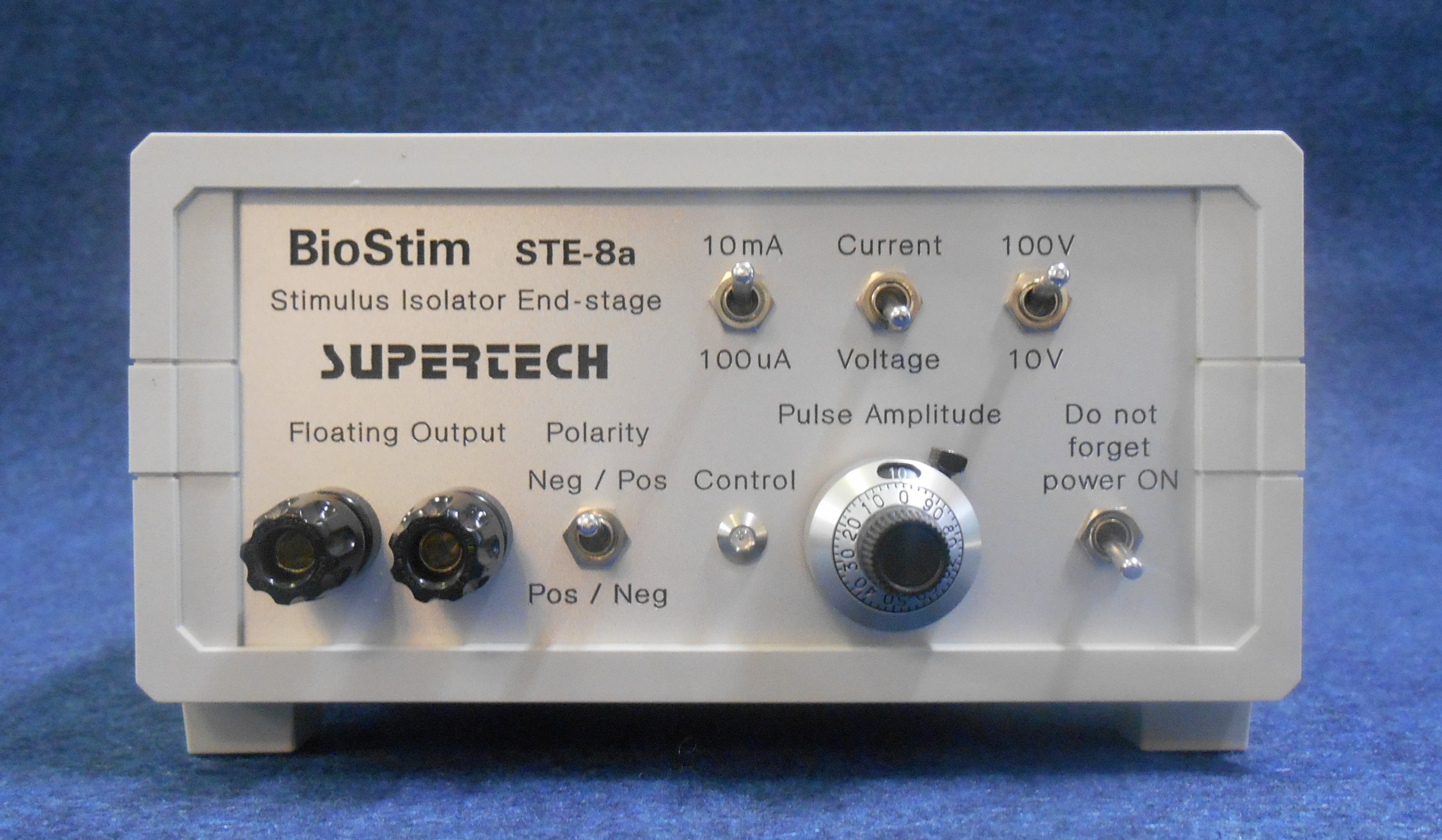
Monopolar Stimulus Isolator (with Rechargeable Battery) STE-8a
Monopolar Battery-supplied Stimulus Isolator STE-8x is one of the most sophisticated stimulus isolator constructions in the choice of Supertech Instruments. Its counterpart is the Bipolar Battery-supplied Stimulus Isolator for bipolar pulse output. The difference between the two versions is, that in the Monopolar Stimulus Isolator there are both a Constant Current generator and a Constant Voltage generator, as well. In the Bipolar Stimulus Isolator there is a Constant Current generator only, but a cumulative charge increase effect does not appear during its usage. Monopolar Stimulus Isolator is supplied from its built-in rechargeable battery pack. Our battery-supplied stimulus isolators are floating equipments. It means, that they have got negligible capacity to the mains or to the ground (> 10 pF).
Monopolar Battery-supplied Stimulus Isolator STE-8x can be used even in the highly noise-sensitive microelectrode experiments (for example multi-electrode patch clamp environments). It passes extremely small, practically zero hum noise into the biological tissue. This version of Stimulus Isolator is optimized for that aspect, that it does not generate any electric hum noise, because of this battery-powered scheme. According to this feature it can be placed close to the experimental object anywhere, even in a seriously shielded environment.
 Click on the picture to get it in full size
Monopolar Battery-supplied Stimulus Isolator STE-8x can be used either in microelectrode experiments or in body surface applications on animals.
There are both a Constant Current generator and a Constant Voltage generator built into this stimulus isolator. The output of the Stimulus Isolator can be switched between Constant Current and Constant Voltage modes on-the-fly, during the experiment. It is a very useful feature, because the first stimulating trials can be carried out in the secure Constant Voltage mode. If the experiment is qualitatively working, the Stimulus Isolator can be switched immediately into Constant Current mode, where the electric charge can be defined and calculated exactly.
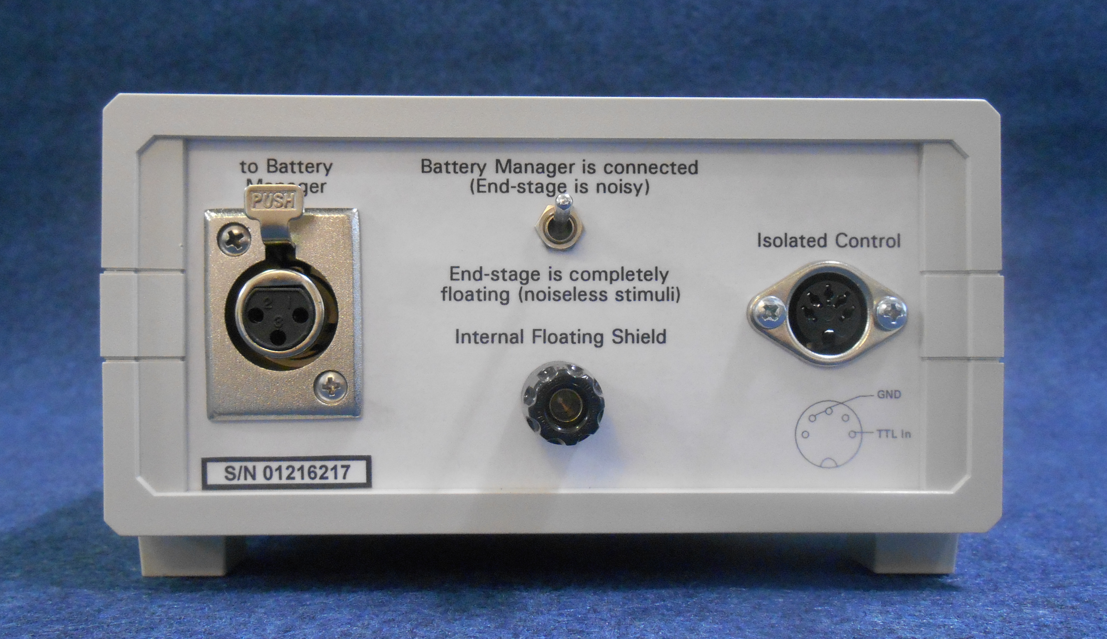
Monopolar Battery-supplied Stimulus Isolator STE-8x is supplied from its built-in rechargeable battery pack. There is an independently orderable accessory: the Battery Manager unit, which is an automatic and precision battery charger and conditioner equipment. Since the Stimulus Isolator is supplied from its built-in battery pack, the charger function, provided by the Battery Manager is indispensable to operate it. With a new battery pack the average operation time (the efficient working period between two charging actions) is approximately 12 hours. If you take care of the battery pack, its lifetime will be at least two years, if the Stimulus Isolator is used every day, the battery pack is charged if necessary, but the battery pack is never over-discharged. These task are carried out by the Battery Manager.
Monopolar Battery-supplied Stimulus Isolator STE-8x has got its own, optically isolated, standard TTL control input. If your PC-based pattern generator (or universal DAQ) program has a hardware interface with standard TTL digital pulse pattern output, it is not necessary to order a BioStim Computer Interface, because the Monopolar Battery-supplied Stimulus Isolator can be connected directly to that digital output.
Specifications / Technical Data
Constant Voltage mode has got two full scale ranges:
10 V
100 V
Constant Current mode has got two full scale ranges:
100 µA
10 mA
Compliance voltage: 120 V
Worst-case amplitude error of the constant voltage and the constant current generators: < 5 %
Nonlinearity of the constant voltage and the constant current generators: < 5 %
Output leakage current is internally trimmed to nearly absolute zero, it is less than 1 µA.
Output overshoot:
< 6 % in constant voltage mode
0 (zero) in constant current mode
Output rise time of the constant current generator:
50 µs (on 1 kOhm load)
70 µs (on 10 kOhm load)
Output fall time of the constant current generator:
60 µs (on 1 kOhm load)
80 µs (on 10 kOhm load)
Output amplitude in the selected range can be set using a 10-turn calibrated helical potentiometer on the front panel.
Resolution of the helical potentiometer: 0.1 %
Protected, 2500 V, optically isolated TTL signal conditioner circuits at the inputs
Double security isolation
Active level at the control inputs: TTL High
Control inputs: TTL compatible, 1 unit-load
Power source: built-in rechargeable battery pack
Nominal voltage of the internal battery pack: 120 V
Nominal capacity of the battery pack: 170 mAh
Compatible with the Battery Manager equipment
The complete User Manual of the Monopolar Battery-supplied Stimulus Isolator and the User Manual of the Battery Manager is available for download.
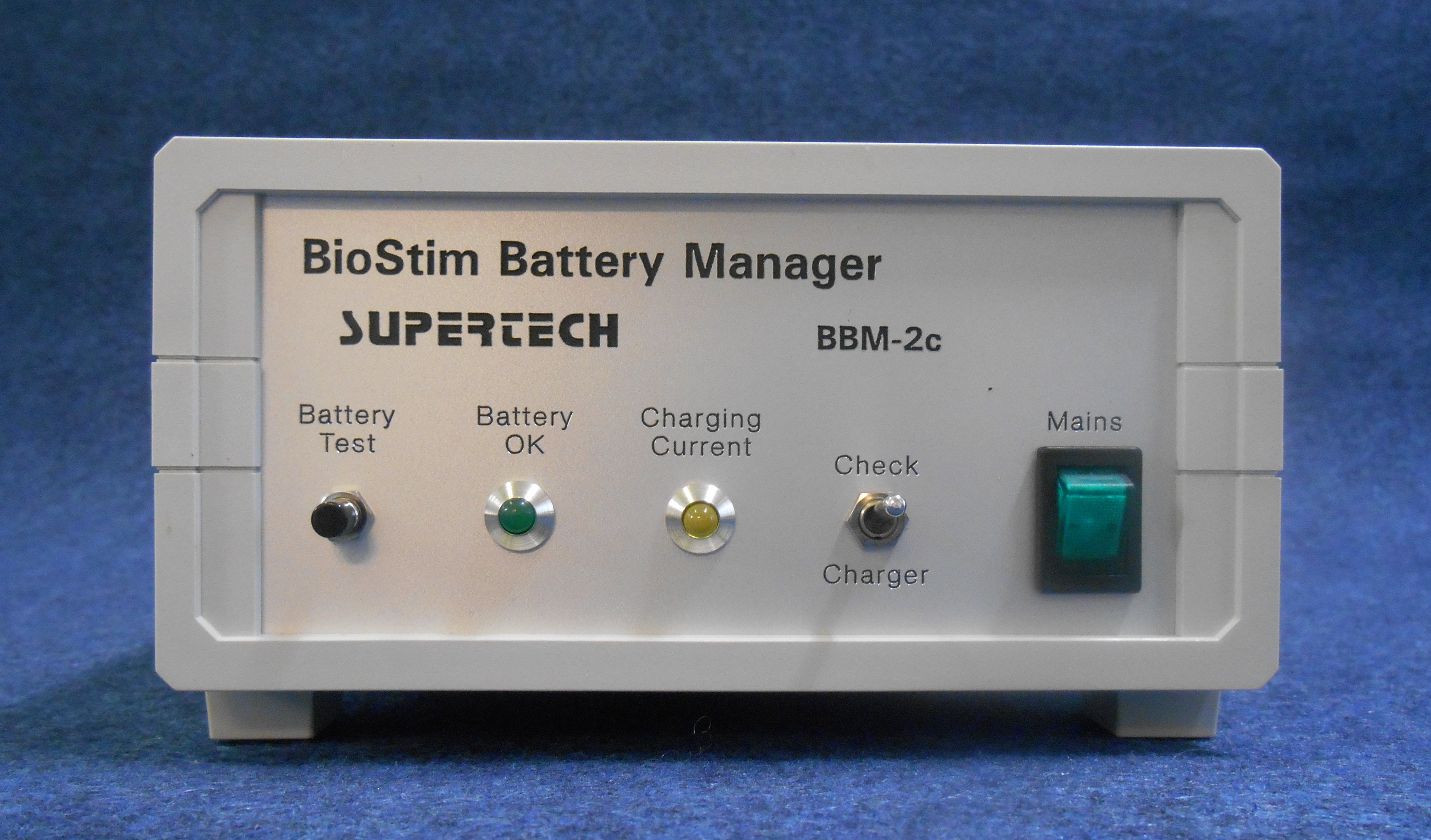
Battery Manager BBM-3a
Battery-supplied Stimulus Isolators have got an additional accessory, the Battery Manager BBM-3x unit, which is an automatic and precision battery charger and conditioner equipment. The nominal voltage of the internal battery pack in the Stimulus Isolators is 120 V, and its nominal capacity is 170 mAh. The only disadvantage of the Battery-supplied Stimulus Isolators is, that they are not very comfortable equipments, because the battery pack requires continuous care of the user. If the Stimulus Isolator is forgotten in switched on state for a prolonged period, the internal battery pack will be ruined. Battery Manager deals with the continuous supervision and maintainance of the internal battery pack of the Stimulus Isolator.
 Click on the picture to get it in full size
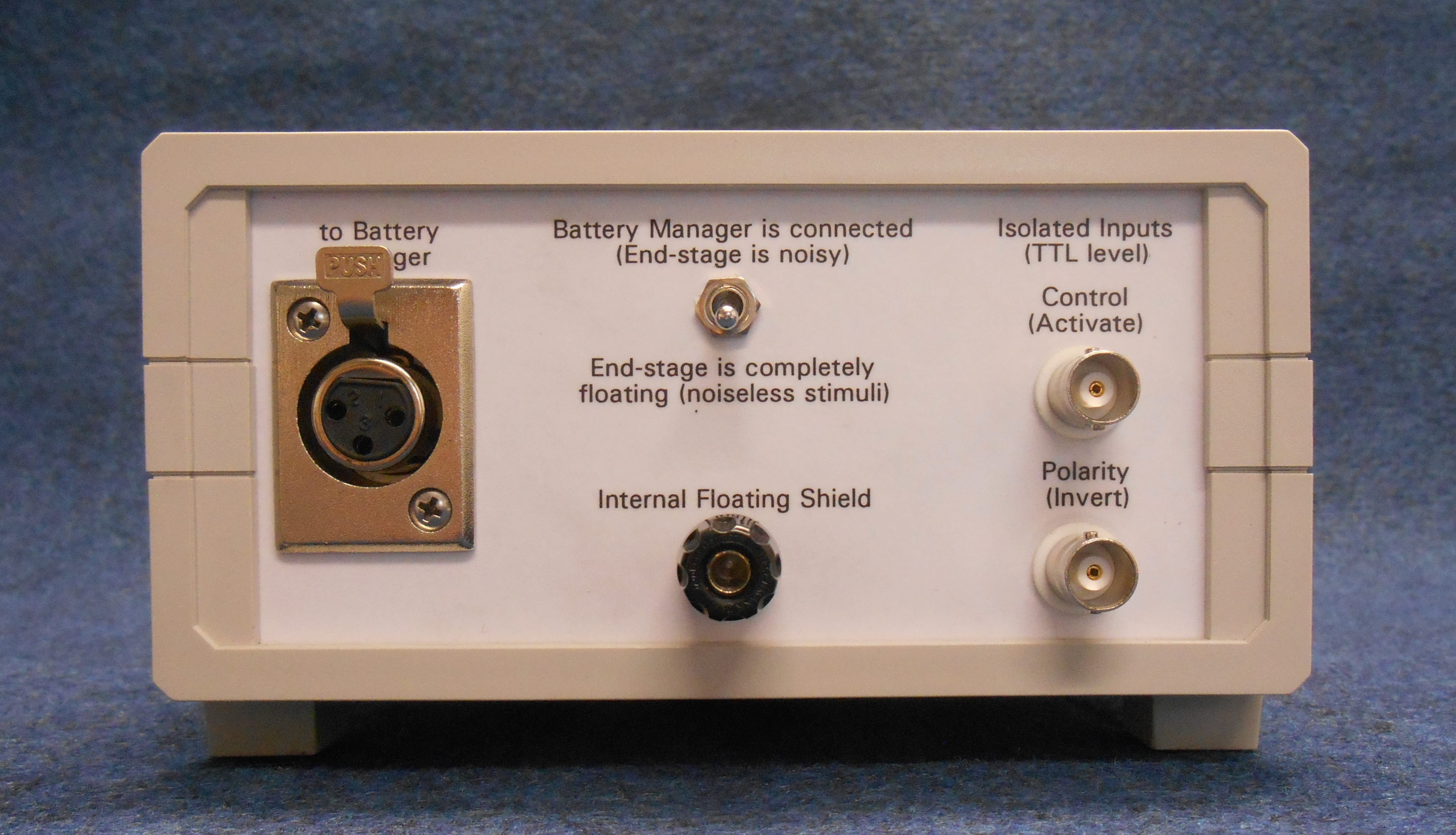
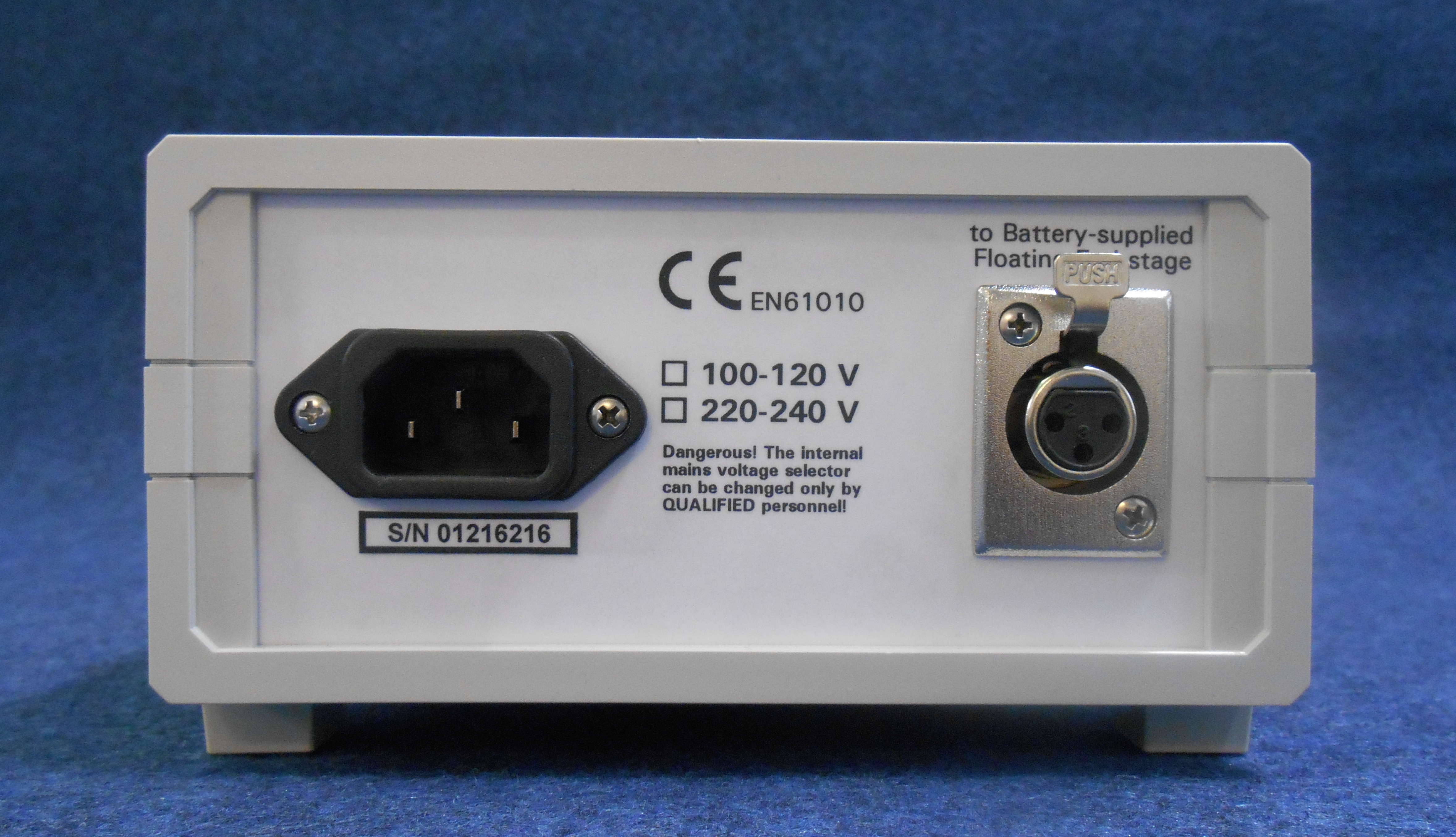
Any model of Battery-supplied Stimulus Isolator and the Battery Manager BBM-3x unit can be connected together with a high-voltage cable. This way the Battery Manager equipment can be placed outside of the shielding Faraday-cage.
The complete User Manual of the Battery-supplied Stimulus Isolator and the Battery Manager is available for download.
Monopolar Stimulus Isolator without Battery STE-7c
This equipment is unavailable as a standard product from stock. In general please choose Monopolar Battery-supplied Stimulus Isolator and Battery Manager.
The stimulating circuitry, the outer looking and all the specifications of this kind of Monopolar Stimulus Isolator are the same as they described above at the Monopolar Battery-supplied Stimulus Isolator. This Stimulus Isolator version without battery is designed for the aspect of the user comfort instead of the aspect of the excellent noise level. However it can be used in many of the microelectrode experiments or in body surface applications on animals. We manufacture it only for unique orders.
You can compare the features of the Stimulus Isolator with or without battery according to these aspects:
1) Electronic floating power supply:
The output circuit is supplied by an internal high frequency power source. The isolation capacitance between the mains plug and the floating output is less than 10 pF. It is good enough for most of the microelectrode experiments. The floating power supply avoids the hum noise efficiently, but generates some switching noise. If you plan to record tiny electric signals simultaneously with another microelectrode from the living tissue, we do not suggest to use an Stimulus Isolator with electronic floating power supply.
2) High voltage battery pack as power supply:
Battery avoids the hum noise and does not generate any electronic noise or disturbance. The battery-based power supply is designed for such applications, where a sensitive signal recording task is running simultaneously with another microelectrode, which is even located close to the stimulating electrode. The Battery-supplied Stimulus Isolator is absolutely "quiet" electronically. The only disadvantage (it is just a financial drawback) is, that you should order a Battery Manager equipment, as well. Battery Manager is described in detail above on this page.
To use the Monopolar Stimulus Isolator Without Battery, you should order a BioStim Controller or a BioStim Computer Interface, too. One of them can provide the necessary low voltage supply for the electronic floating power supply and the universal TTL logic inputs for the operation of the Stimulus Isolator.
The complete User Manual of the Monopolar Stimulus Isolator is available for download.
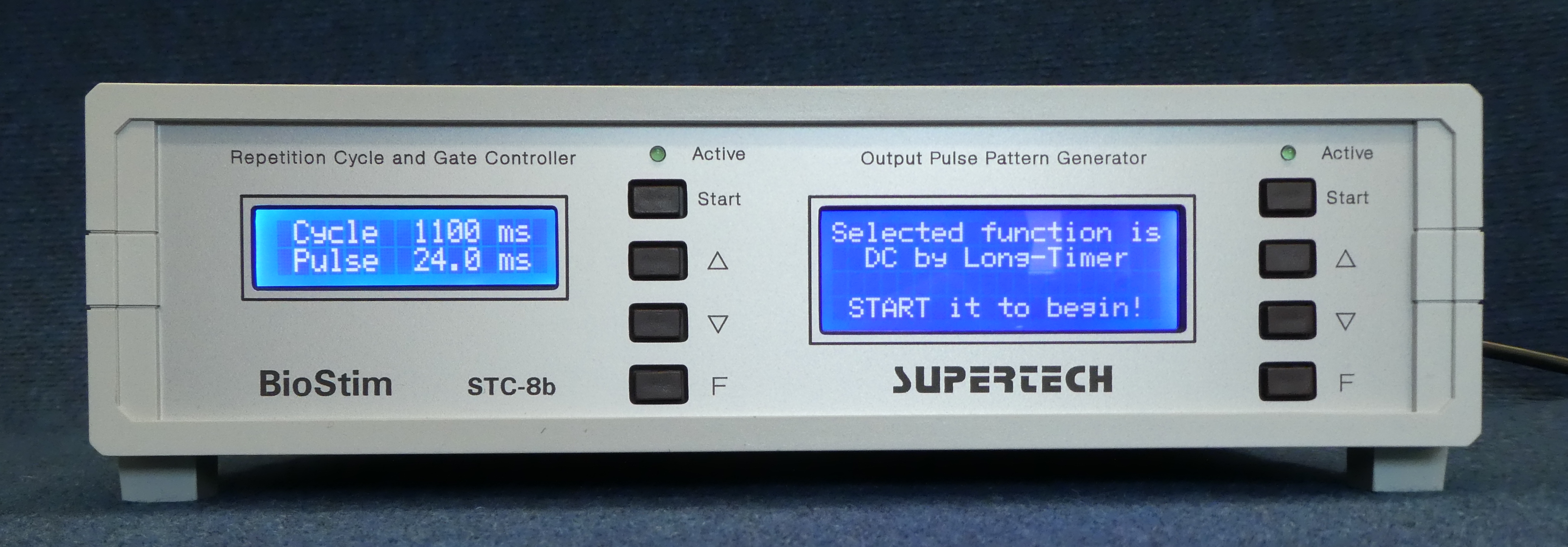
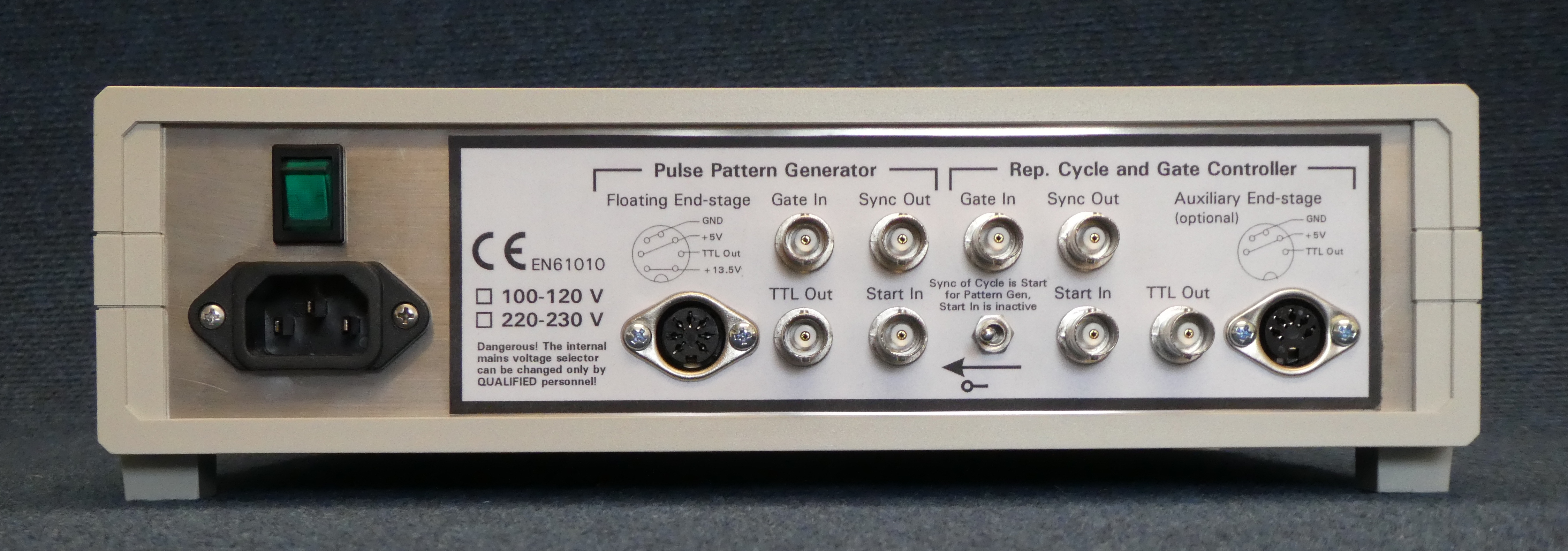
BioStim Dual-processor Controller STC-8b
In this description BioStim Dual-processor Controller is simply called BioStim Controller.
BioStim Controller is a dual-processor equipment. There are two independent RISC microcontrollers built into one cage. One of them, the Repetition Cycle and Gate Controller can be used to generate the periodic repetition trigger events, or it can be used as a gate generator to enable or disable the output pulse sequence generated by the Pulse Pattern Generator. The other microcontroller is the Pulse Pattern Generator. It is used to generate the different output pulse sequences (as listed below).
 Click on the picture to get it in full size
The accuracy of the time parameters in BioStim Controller are guaranteed by internal crystal pacers. All the programmed time parameters are stored in built-in nonvolatile memories. They hold the previously used values during switched off periods. Easy programming operations are carried out in menu system, with 4-button keypads. The displays of the microcontrollers are 4 x 20, and 2 x 16 character alphanumeric models with backlight to provide good visibility.
BioStim Controller (together with one of the Stimulus Isolators) can be used as a stand-alone stimulator, but both of its microcontrollers have got bi-directional digital control capabilities: Start Input, Gate Input, and Synchron Output. These TTL-compatible control signals offer a huge versatility in the different applications. BioStim Controller can be started externally (with rising edges at Start Inputs) from another equipment (for instance a PC), or it can be the master synchron generator (if the external equipments are triggered from its Synchron Outputs), as well.
BioStim Controller has got nonvolatile memories to store all parameters of the functions. If you use the equipment in a fixed application, you should program it one time only. If you switch the BioStim Controller on, it checks, which function was used last time. After it the parameters used by the actual function are checked. If the parameters have got valid values preset, the last used function will be started automatically.
The human patient and user security instructions to use BioStim stimulators is downloadable. This document is available in Hungarian language.
The complete User Manual of the BioStim Controller, and the BioStim Computer Interface is available for download.
The Operating Modes of the BioStim Controller
Programming Conventions and Definition of Terms in the Firmware
The functions are categorized into two groups. The first group contains the 'single' functions. 'Single' functions are initiated by the START event. After a START event they generate their sequence one time only (an example is Single Burst). The other category is the group of the 'repetitive' functions. They repeat their sequence periodically (an example is Continual Bursts).
A subcategory of the 'single' functions is the group of the 'delayed' functions. They are the same as their appropriate 'single' equivalents, but a programmable delay is occurring at the beginning of the sequence before the first Output pulse appears.
START event means a key-press on START button or a TTL rising edge appearing at the Start Input. The two source of Start event can be used together or independently any time (they are in logical OR relation).
You can clear all stored parameters if you press and hold F button down while BioStim Controller is switched on. During programming actions the equipment checks the validity of the actual value entered. If you try to accept (with F button) a number out of range, the firmware will not allow it. If more than one parameters are incoherent, you will be asked to correct them.
UP and DOWN button is used to navigate in menus and to modify parameter values up or down, respectively. F button is used to select a menu item or accept an input parameter value. Furthermore, F button is used to cancel a function if it is running. If you cancel a function with F button, you will get an access to Function Choice menu. START button is used to start the sequence of pulses, if a 'single' or a 'delayed' function is selected actually. The 'repetitive' functions can be interrupted temporarily with START button (and they can be restarted again with it).
Operating Modes of the Repetition Cycle and Gate Controller in the BioStim Controller
Repetition Cycle
This function can be used to generate periodic repetitive trigger events in such cases, when the BioStim Controller is the master synchron generator of the data acquisition process (in those cases, when the external data acquisition equipment, such as a PC, is triggered from its Synchron Output). In this function the Synchron Output of the Repetition Cycle and Gate Controller provides repetitive Start events for the Pulse Pattern Generator, on which any of the ‘single’ patterns should be selected. To use the Repetition Cycle function the Synchron Output of the Repetition Cycle and Gate Controller should be connected to the Start input of the Pulse Pattern Generator with the appropriate switch at the back side of the BioStim Controller. The repetition cycle time (Tc) can be set from 80 ms - 60 sec, with 10 ms of resolution. A wide (50 ms) Synchron pulse is generated at the beginning of every Repetition Cycle. These Synchron pulses are the synchron pulses of the whole time sequence, if the Repetition Cycle function is used and a ‘single’ pulse pattern is selected on the Pulse Pattern Generator. The Repetition Cycle and Gate Controller has got its own TTL-compatible Output, which is independent from the Output of the Pulse Pattern Generator. The Output pulse of the Repetition Cycle and Gate Controller (0.1 - 24.9 milliseconds in width, with 0.1 ms of resolution) can be optionally used for any other controlling task (for example muting the input of the preamplifier for a programmed period before appearing and during the stimulating pulse at the Output of the Stimulus Isolator).
Gate Generator
This function can be used to generate a programmed enabling period for the Gated Continual function of the Pulse Pattern Generator. To use the Gate Generator function the TTL-compatible Output of the Repetition Cycle and Gate Controller should be connected to the Gate Input of the Pulse Pattern Generator with an external BNC cable at the back side of the BioStim Controller. This combination of functions can be used to produce very long bursts of pulses. The duration of the burst is defined by the length of the output pulse set on the Repetition Cycle and Gate Controller. The duration of the pulses and the pauses should be programmed at the Pulse Pattern Generator in its Gated Continual function. The gate time (Tg) can be set from 80 ms - 60 sec, with 10 ms of resolution. A wide (50 ms) synchron pulse is generated at the beginning of every Gate periods. These synchron pulses are accessible at the Synchron Output of the Repetition Cycle and Gate Controller.
Operating Modes of the Pulse Pattern Generator in the BioStim Controller
The actually available 12 operating modes (in other words the choice of the pulse patterns) of the Pulse Pattern Generator in the BioStim Controller are presented in this document. They have got a graphical interpretation to explain them in fine details. In some experimental situations there are more than one function with which a paradigm can be carried out. You should always consider, which function is the best one for your special stimulating task.
BioStim Computer Interface STI-4a
There is an alternate equipment in our product choice to substitute the BioStim Controller in that cases, when a computer software is used to generate the sequence of stimulating pulses. BioStim Computer Interface has got a universal connector compatible with any Stimulus Isolator manufactured by Supertech Instruments. BioStim Computer Interface has got a built-in power supply unit optimized for the Stimulus Isolators and it has two universal TTL-compatible digital input connectors. Its TTL inputs are configured in logical OR function internally. The TTL gold standard describes the voltage and load specifications of the inputs and outputs of a logic system, what is supplied from 5V. Nowadays most of the microcontrollers and logic systems use 3.3V of internal supply voltage. The logic signal inputs of the BioStim Computer Interface are universal, they accept the logic levels of the 3.3V, non-standard-TTL systems correctly with optimal noise margins, too.
Basically BioStim Computer Interface realizes (by hardware) the DC via Control function (see later in this description) of the BioStim Controller. If an appropriate software is used, what can generate the stimulating pulse trains, it is not necessary to order a BioStim Controller at all, it is enough to use the BioStim Computer Interface instead. The disadvantage of this arrangement is, that a fast computer and a time-critical multitasking DAQ software is necessary to be used. An independent, universal, stand-alone stimulator can be formed only by using the BioStim Controller.
The complete User Manual of the BioStim Controller and the BioStim Computer Interface is available for download.
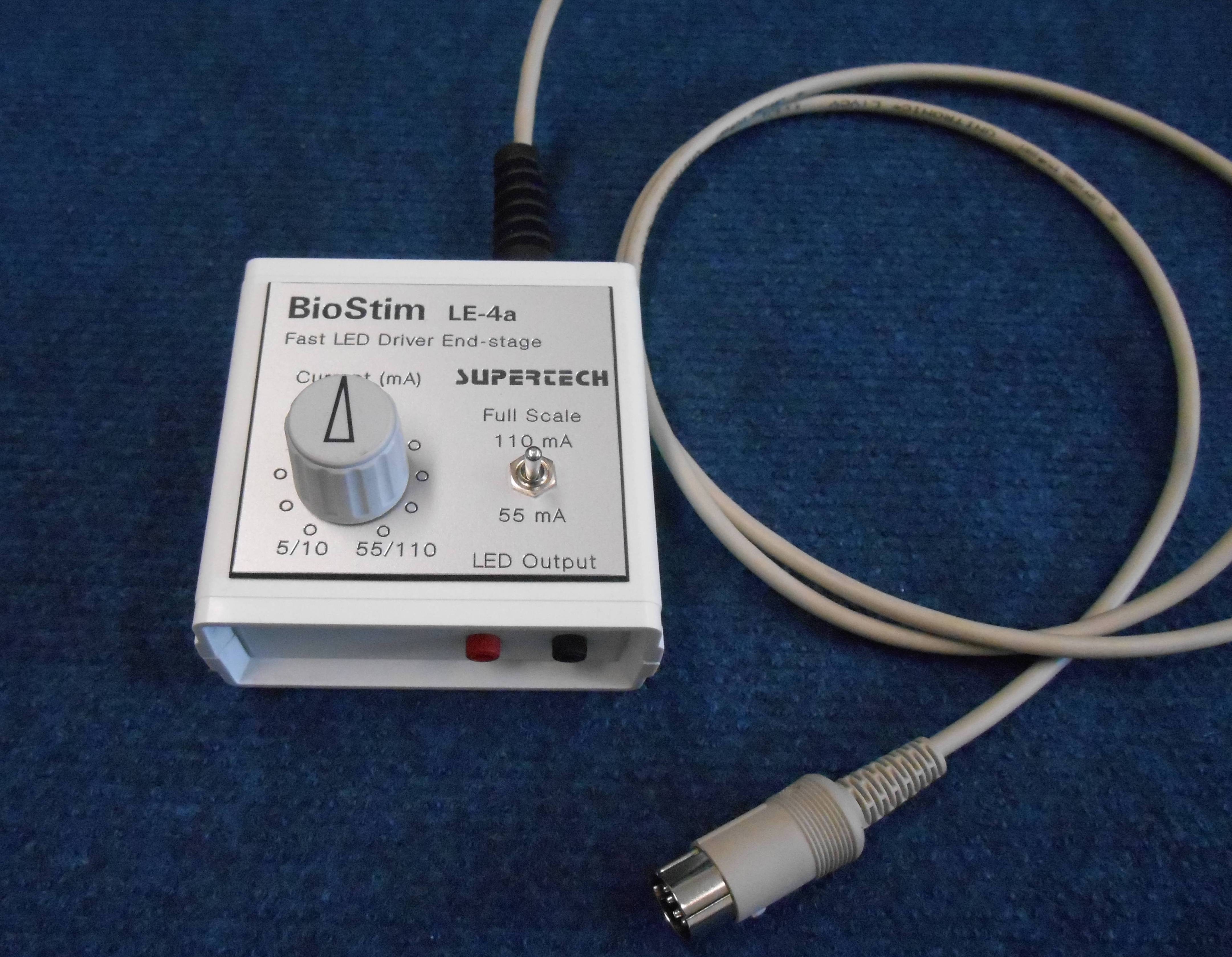
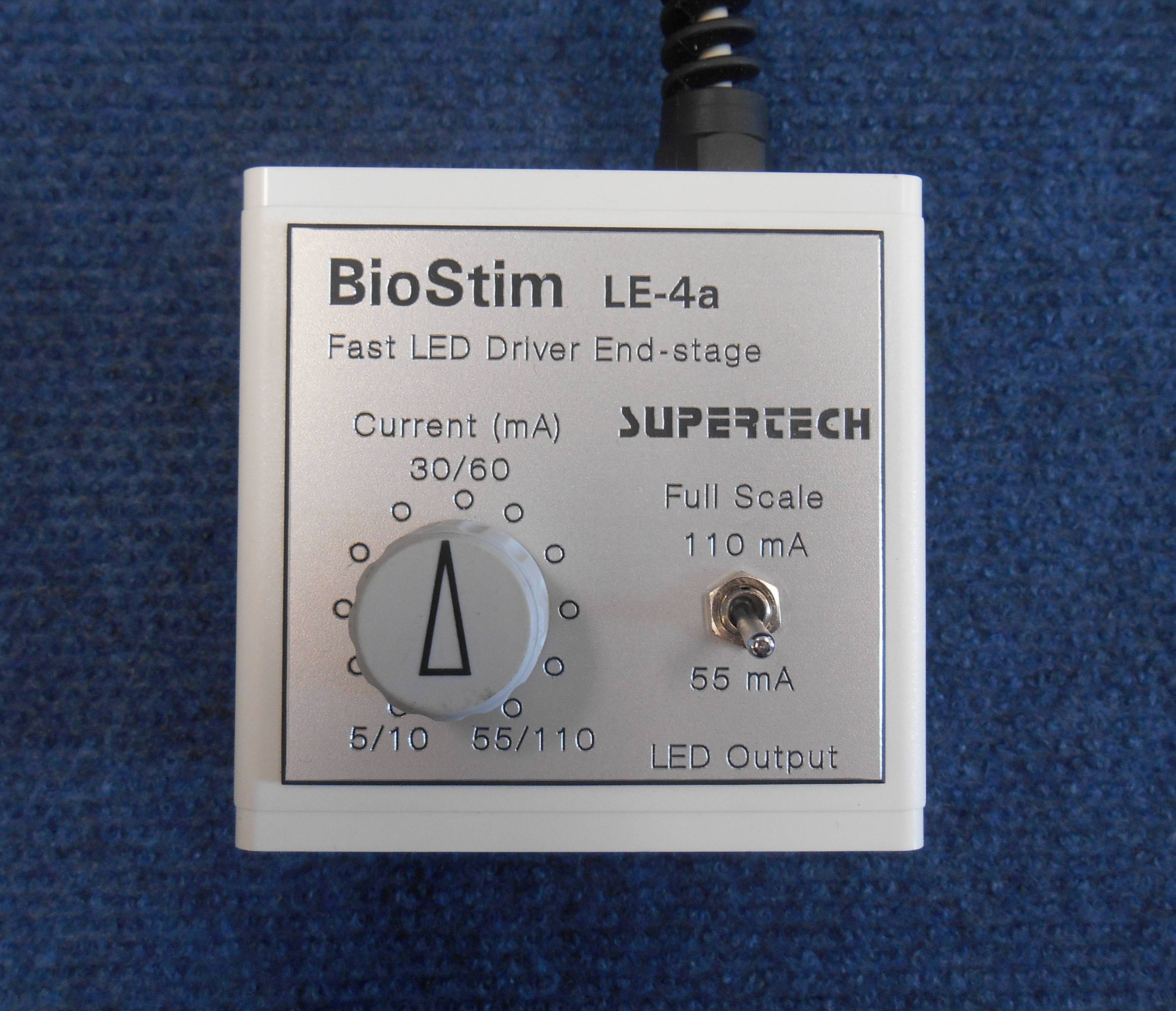
Fast LED Driver LE-4a
Fast LED Driver LE-4a can be used for optogenetics, retinography and other light stimulating applications controlled by the BioStim system. LE-4a can drive any kind of LED directly with calibrated current, independently of the LED model. LE-4a LED Driver is compatible either with BioStim Dual-processor Controller or with BioStim Computer Interface. LE-4a contains a built-in accurate constant current generator and a high speed gating circuit for extremely fast switching of the LEDs.
There is a very special feature implemented in the design. It is overdrive protection. You can read about this feature and you can see the other LED Driver models on the Optogenetics page.
 Click on the picture to get it in full size
Specifications / Technical Data
The selectable ranges of the output current:
5 to 55 mA in 11 steps (5 mA each step)
10 to 110 mA in 11 steps (10 mA each step)
Compliance voltage of the current generator: 13.5 V
Worst-case error of the output current generator: < 2 %
Active current sink circuit to eliminate the parasitic charge holding effect of LEDs
Overdrive Protection Circuit: the full scale is never overridden
To use the LE-4x Fast LED Driver, you should order a BioStim Controller or a BioStim Computer Interface, as well, because one of them is necessary to provide the supply voltage and the control signal for the Fast LED Driver. The stand-alone LED Drivers are published on the Optogenetics page.
Fiber Optic Transmitter and Fiber Optic Receiver
They have been designed to use the BioStim Universal Biological Stimulator System in MRI and FMRI labs. The Stimulus Isolators manufactured by Supertech Instruments are MRI-compatible. The Fiber Optic Transmitter / Receiver equipment pair is a single-channel, high voltage tolerant, noise insensitive, isolated, digital signal transmission line. Due to them the Stimulus Isolator can be positioned close to the animal in the high magnetic field area while the BioStim Controller or the BioStim Interface can be located in the control room.
The top of its basic application field the Fiber Optic Transmitter equipment can be used for optogenetics, rtinography and other light stimulating applications in MRI and FMRI labs. In other words it can behave as a Remote Optical Stimulator. Its output light can be transmitted directly by the optical fiber to the animal located in the high magnetic field. The wavelength of the Fiber Optic Transmitter is 660 nm. Its output optical (light) power is 1mW.
Please call or email us for further information.
Prices
You can find the general warranty and shipping conditions in the beginning of the Services page.
Monopolar Battery-supplied Stimulus Isolator STE-8a, including the built-in rechargeable battery pack: 840 EUR
Bipolar Battery-supplied Stimulus Isolator BSE-4x, including the built-in rechargeable battery pack: 1260 EUR
Battery Manager BBM-3a: 576 EUR
BioStim Controller STC-8b (dual-processor version): 1080 EUR
BioStim Computer Interface STI-4a: 480 EUR
120V rechargeable battery pack STI-Bat-1 (for replacement purpose): 288 EUR
Fast LED Driver LE-4a: 276 EUR
Fiber Optic Transmitter / Remote Optical Stimulator FOT-1 (660 nm, 1mW), single-channel equipment in a small plastic enclosure, compatible with the BioStim Controller or BioStim Computer Interface: 324 EUR
Fiber Optic Receiver FOR-1 (660 nm), single-channel equipment in a small plastic enclosure, supplied from a wall plug DC power supply (included in the price): 288 EUR
Optical Fiber OF-5A, 5 m, assembled with connectors: 60 EUR
![]()
![]()
![]()
![]()
![]()
![]()
![]()
![]()
Copyright @ Supertech Instruments - since 1991