
![]()
![]()
![]()
![]()
![]()
![]()
![]()
![]()
Engineering Creativity for Neuroscience
BioAmp DC Universal Biological Amplifier System
General purpose bio-amplifiers with DC recording capability. BioAmp DC is perfect for all electrophysiological applications. Most of the competitor amplifiers are not able to record DC potentials. BioAmp DC is optimized for accurate DC amplification, while offering wide bandwidth, as well. In other words one of its high pass filter positions is 0 Hz. Furthermore there are precision offset voltage correction modules (analog and digital) as orderable options. BioAmp system can be configured 1 to many channels modularly.
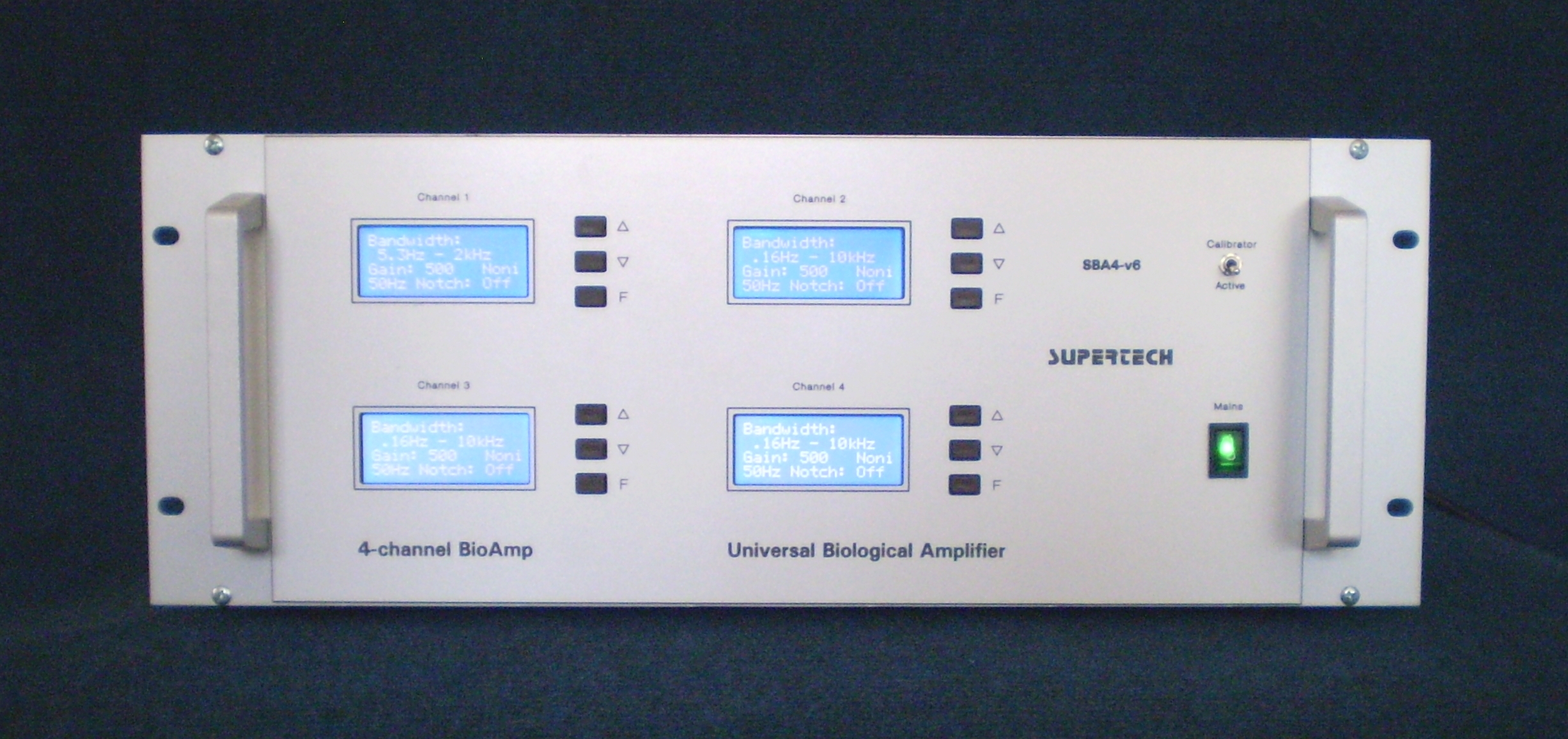
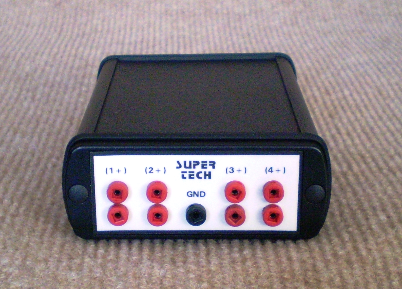
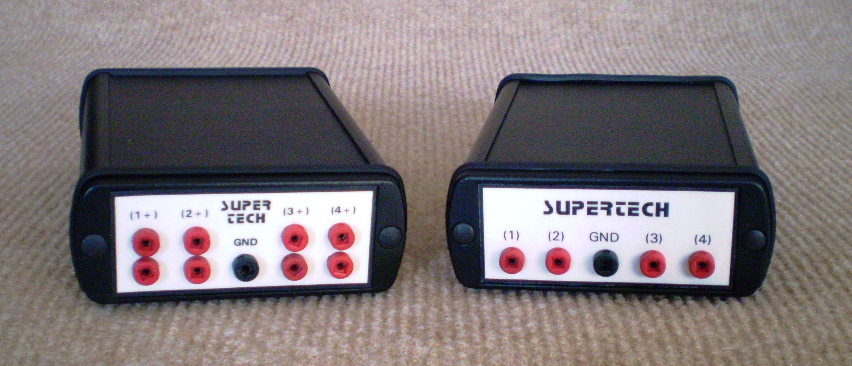
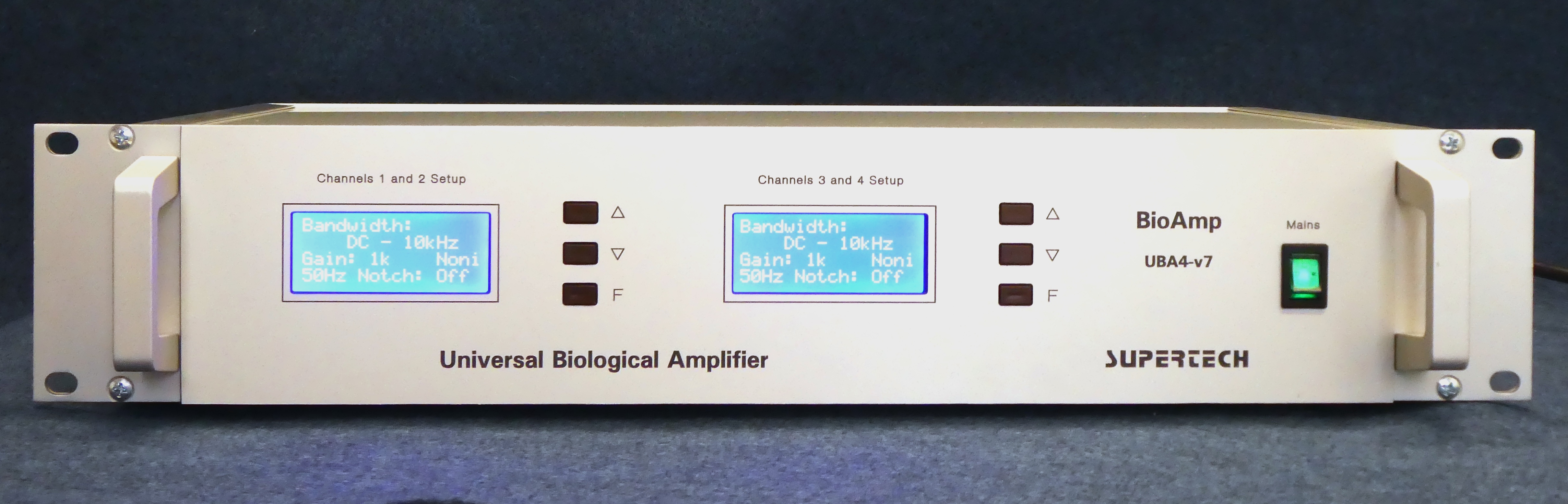 An example: 4-channel BioAmp. Click on the picture to get it in full size
BioAmp's Main Fields of Applications
• Multi-channel DC recording (e.g. in epilepsy research)
• Electroencephalography (EEG)
• Microelectrode recording (Single- and multi unit activity, Juxtacellular recording, Field Potential, Motor Units, etc.)
• Evoked Potentials in the brain (EVP)
• Potentials recorded from the surface of the body (ECG, EMG, ERG, etc.)
• Heart micropotentials (HIS-bundle, Late Potential, etc.)
• Multi-channel applications (EEG Brain Mapping, Cortical Depth Mapping, etc.)
Main Amplifier V.7
General Description
BioAmp is a programmable amplifier, but it has no sampling circuits in the signal path at all. In other words, it is controlled by a built-in microcontroller or a remote computer, but it has got only high-performance, low noise, low distortion analogue amplifier circuits. One can say, that it is old fashioned. We keep this traditional construction style, because it provides supreme accuracy and unsurpassable linearity. This full-analog feature is indispensable when you use averaging techniques for processing its output signal. The internal Amplifier Setup Controller and the optional digital port (which offers remote control facility from a PC) are optically isolated from the amplifier stages. This way we could connect all the advantages of high accuracy analogue amplifier circuits and easy usage of digital control.
Although BioAmp is programmable equipment, it does not need a separate computer to work. According to this fact, it can be used as a stand-alone amplifier (while possessing an optional serial port to communicate with a PC). This stand-alone feature is very comfortable, because the computer is always given, but it should be used to collect and to process the experimental data. Every Amplifier Setup Controller on the front panel has got a 3-button keypad and menu-driven internal firmware, so it is very friendly to use.
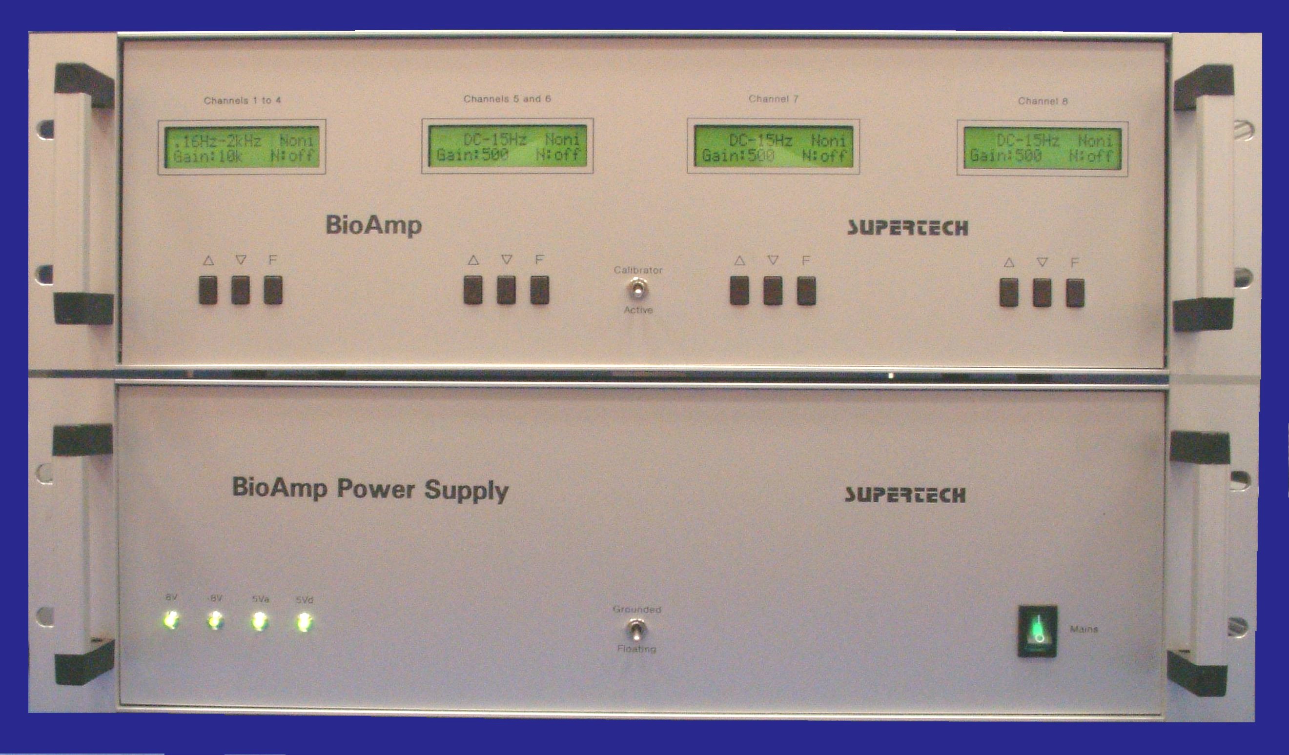
The internal structure of BioAmp is modular, so the number of the amplifier channels and the number of the Amplifier Setup Controllers built in the equipment can be decided independently. Only the aspects of the application field should be considered when we decide, how many amplifier channels and how many Amplifier Setup Controllers will be placed in the equipment cage (for example it is comfortable to use only one Amplifier Setup Controller to program all the EEG channels together, but another Amplifier Setup Controller should be used if there is a single unit channel in the system, and a third Amplifier Setup Controller is necessary, if there are further channels for ECG). The front plate Amplifier Setup Controller drives an internal serial bus. On this bus the Amplifier Setup Controller is the master and the amplifier boards are the slaves. The slaves cannot be addressed on the bus. All slaves that are connected to the bus receive the commands from the master at the same time. An Amplifier Setup Controller can drive any number of amplifier boards. The slaves are wired on the bus on a fixed way. This is the reason, why usually more than one Controller is located on the front plate. Examples: a 16-channel equipment can be designed with three Amplifier Setup Controllers on the front: Arrangement (1): channels 1 to 8 are connected to the 1st Controller, channels 9 to 12 are connected to the 2nd Controller and channels 13 to 16 are connected to the 3rd Controller. Arrangement (2): channels 1 to 12 are connected to the 1st Controller, channels 13 to 15 are connected to the 2nd Controller and only channel 16 is connected to the 3rd Controller. Other convenient arrangements can be created, too.
BioAmp amplifier system offers a very reasonable price level in comparison to the number of channels.
The model number identification convention of the BioAmp system is the following. Value of x is the number of the channels in the equipment:
• SBAx-v7: Simplified biological amplifier, with DC recording capability, without Digital Offset Voltage Controller
• UBAx-v7: Universal, internally modular biological amplifier, with DC recording capability, without Digital Offset Voltage Controller
• DBAx-v7: Universal biological amplifier with analog and digital DC offset correction feature (potentiometers in the preamp and Digital Offset Voltage Controller in the main amplifier)
BioAmp DC is an extremely versatile construction. Before ordering your amplifier, please consult with our development engineer to find the optimal and most comfortable offset correction method for your given signal recording paradigm.
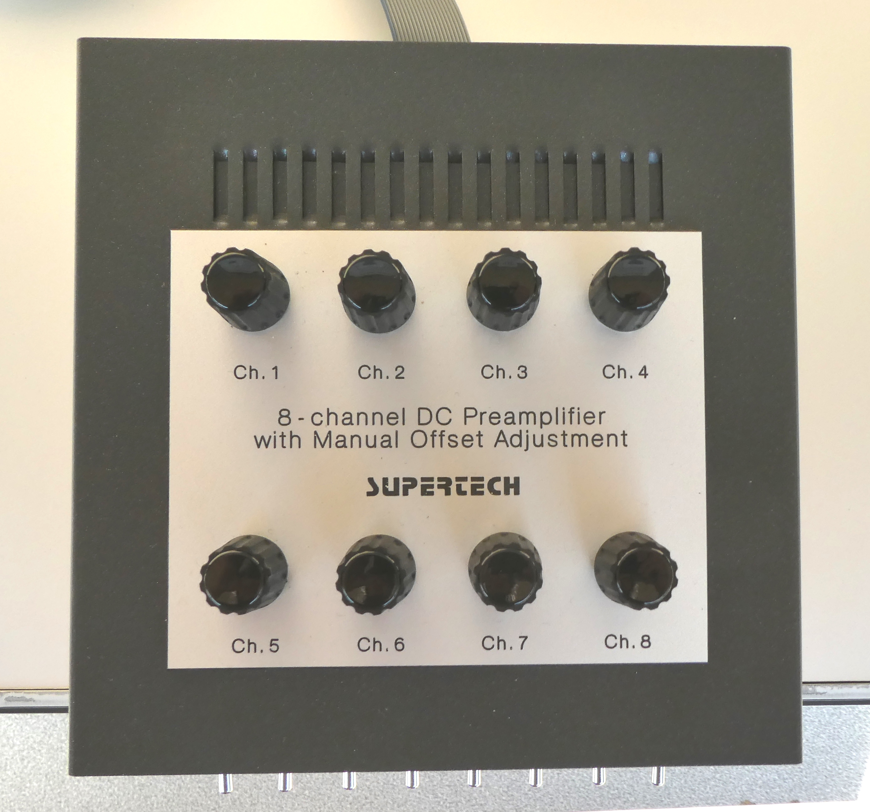
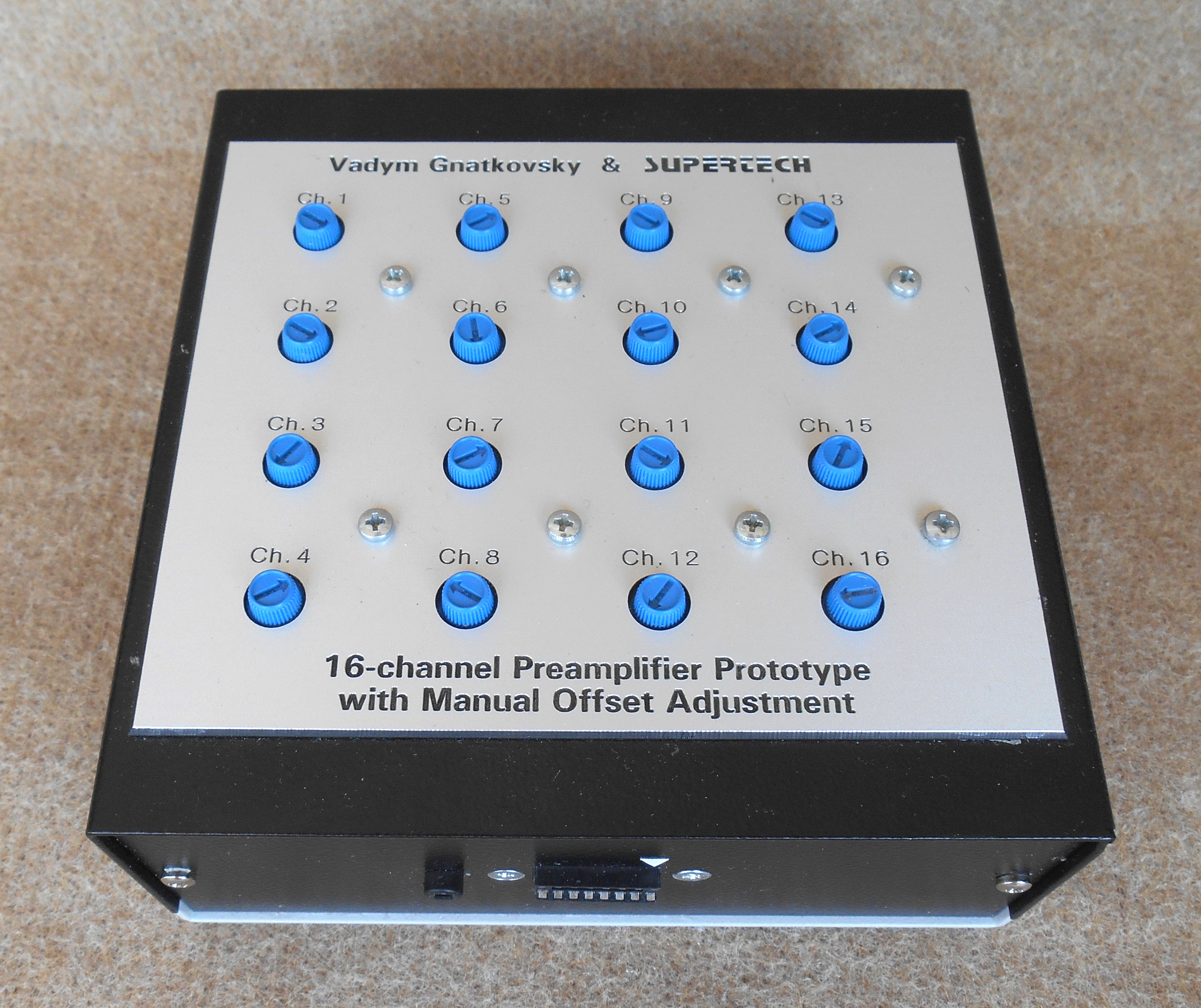
Picture Gallery of a Few Different BioAmp Main Amplifiers
Click on the picture to get it in full size
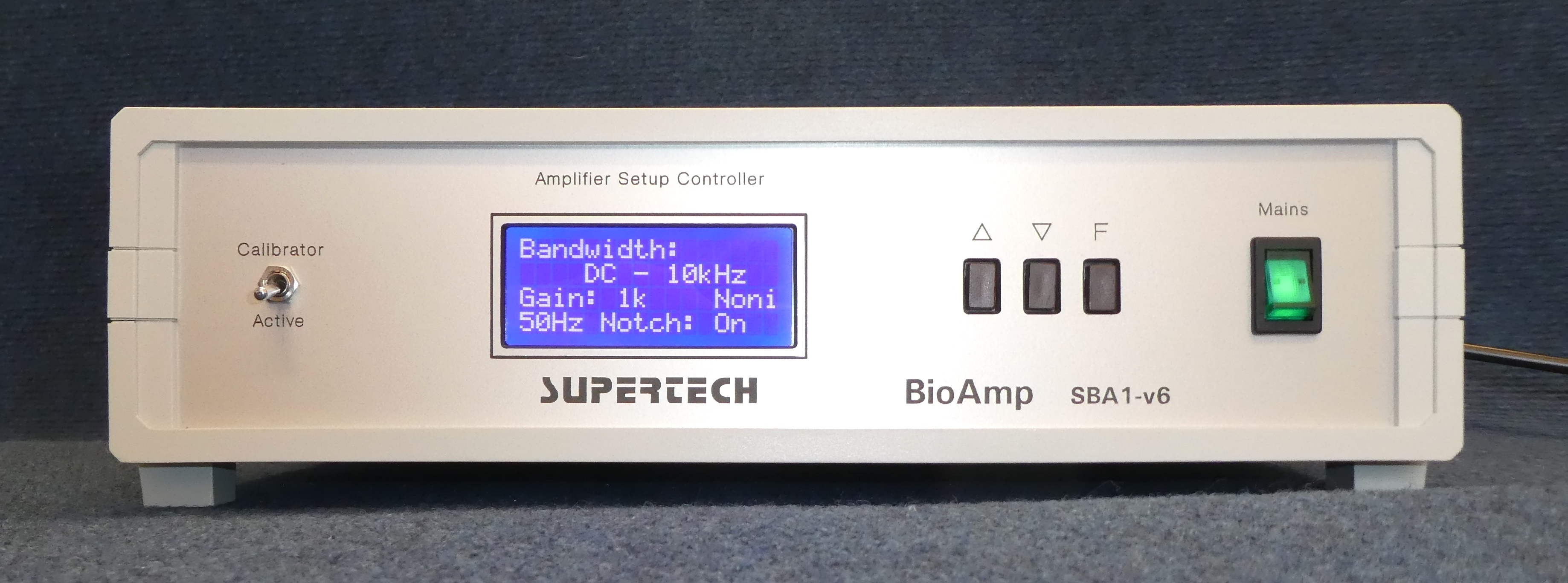 Single-channel basic model
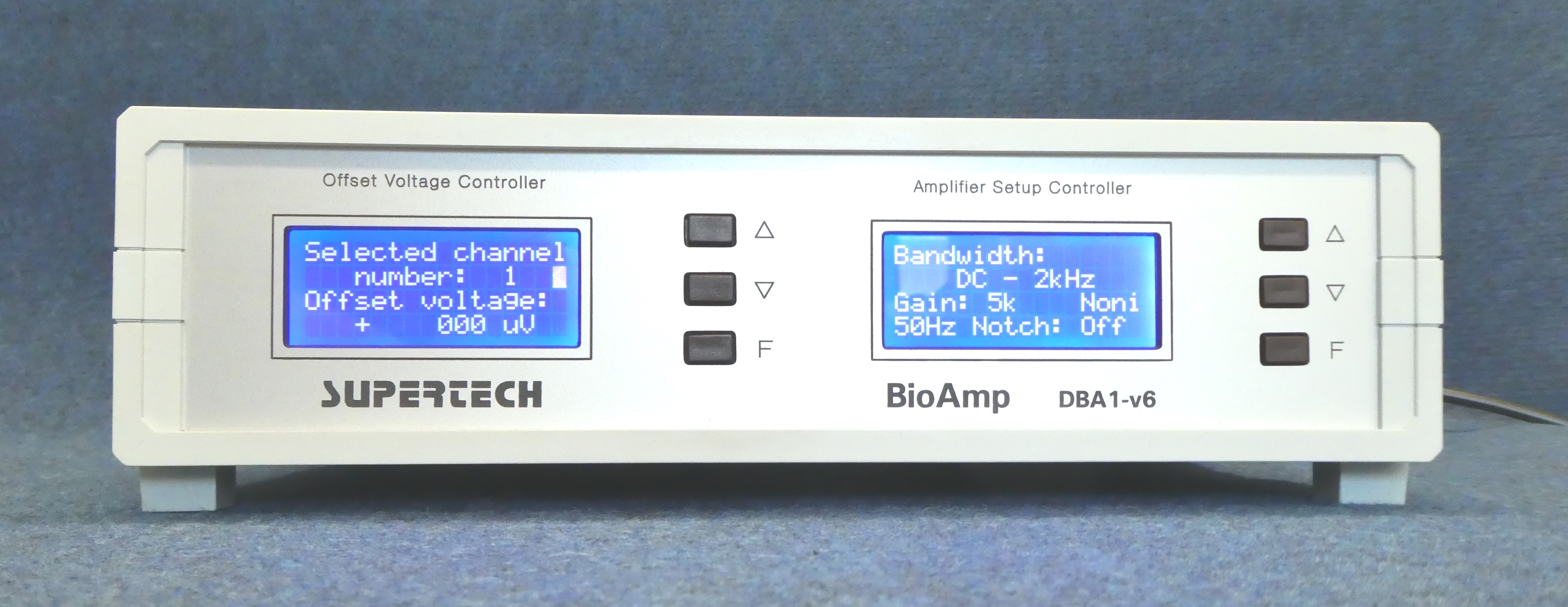 Single-channel DC model with offset voltage controller
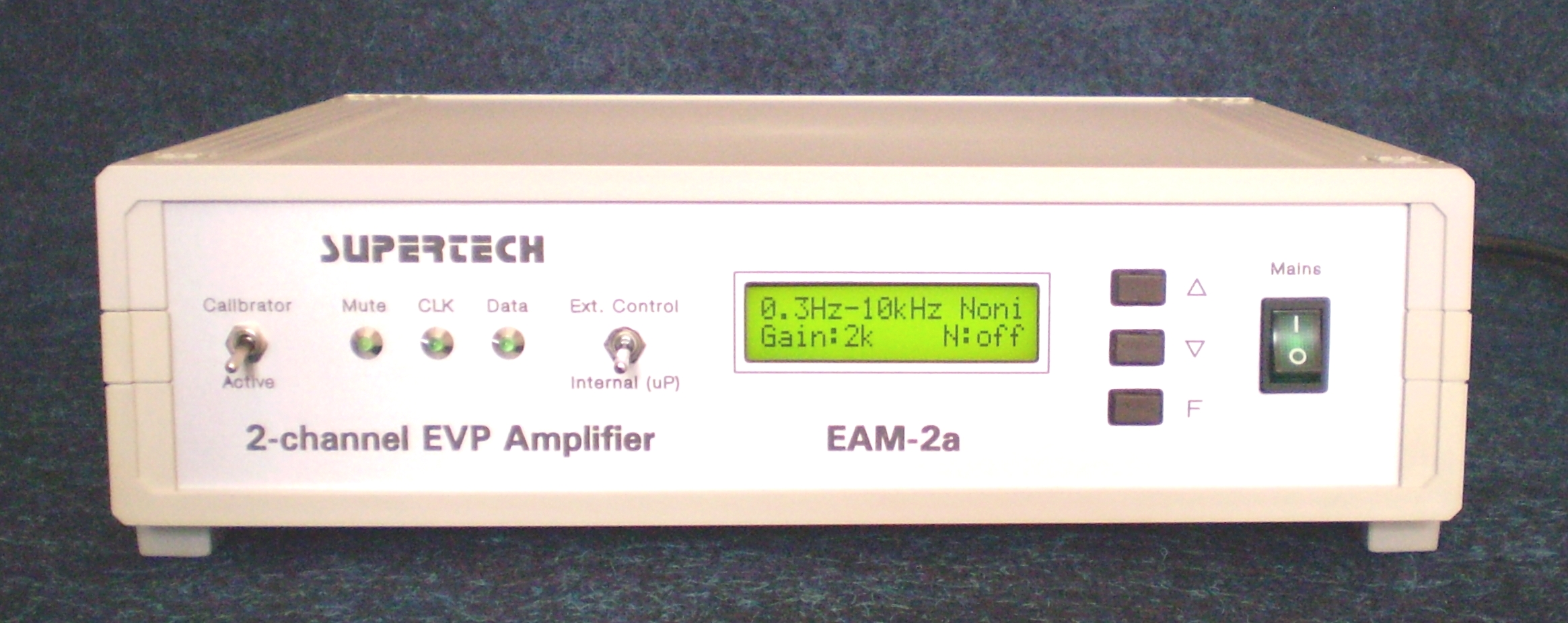 Dual-channel task-specific model, evoked potential analyzer
 4-channel model
 8-channel basic model
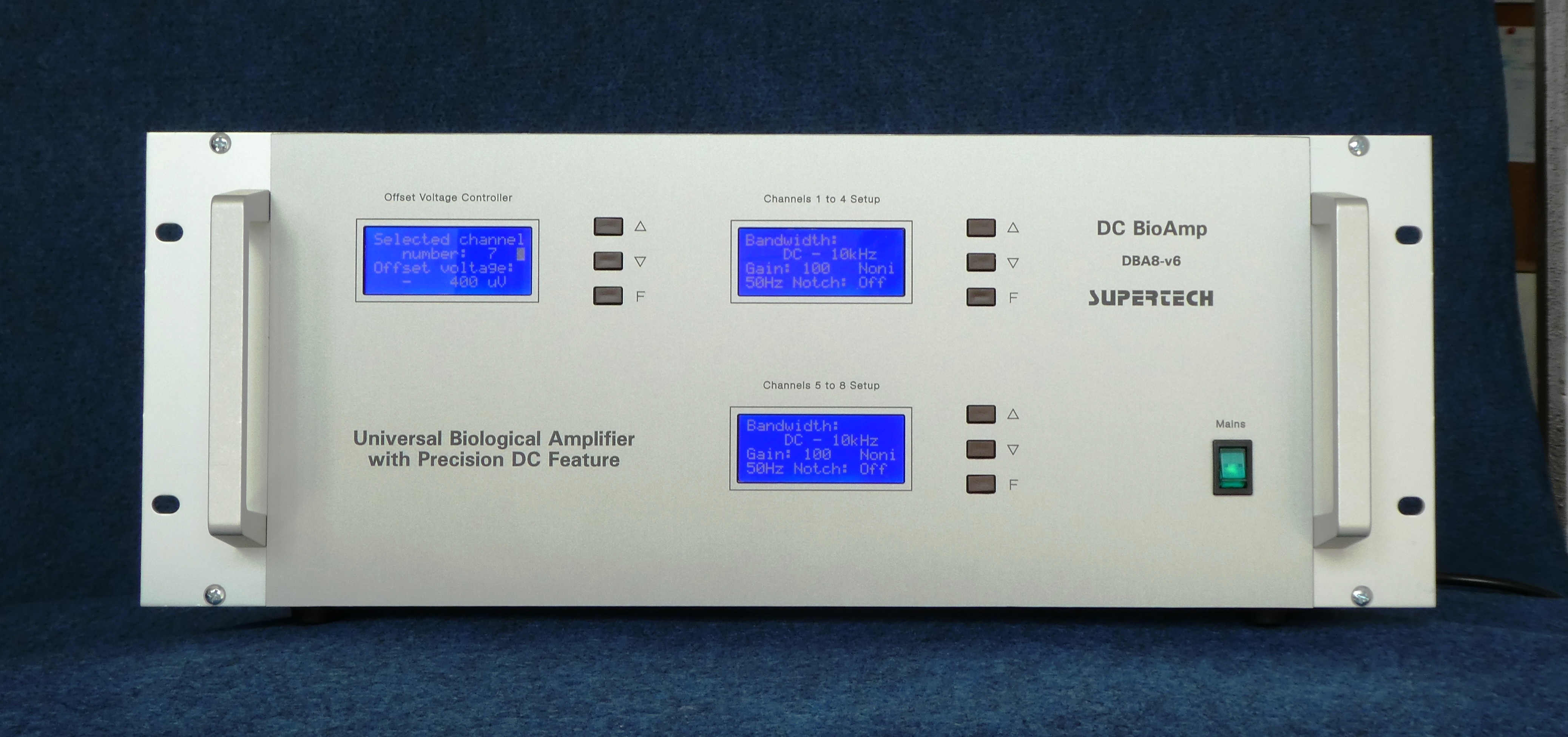 8-channel DC model
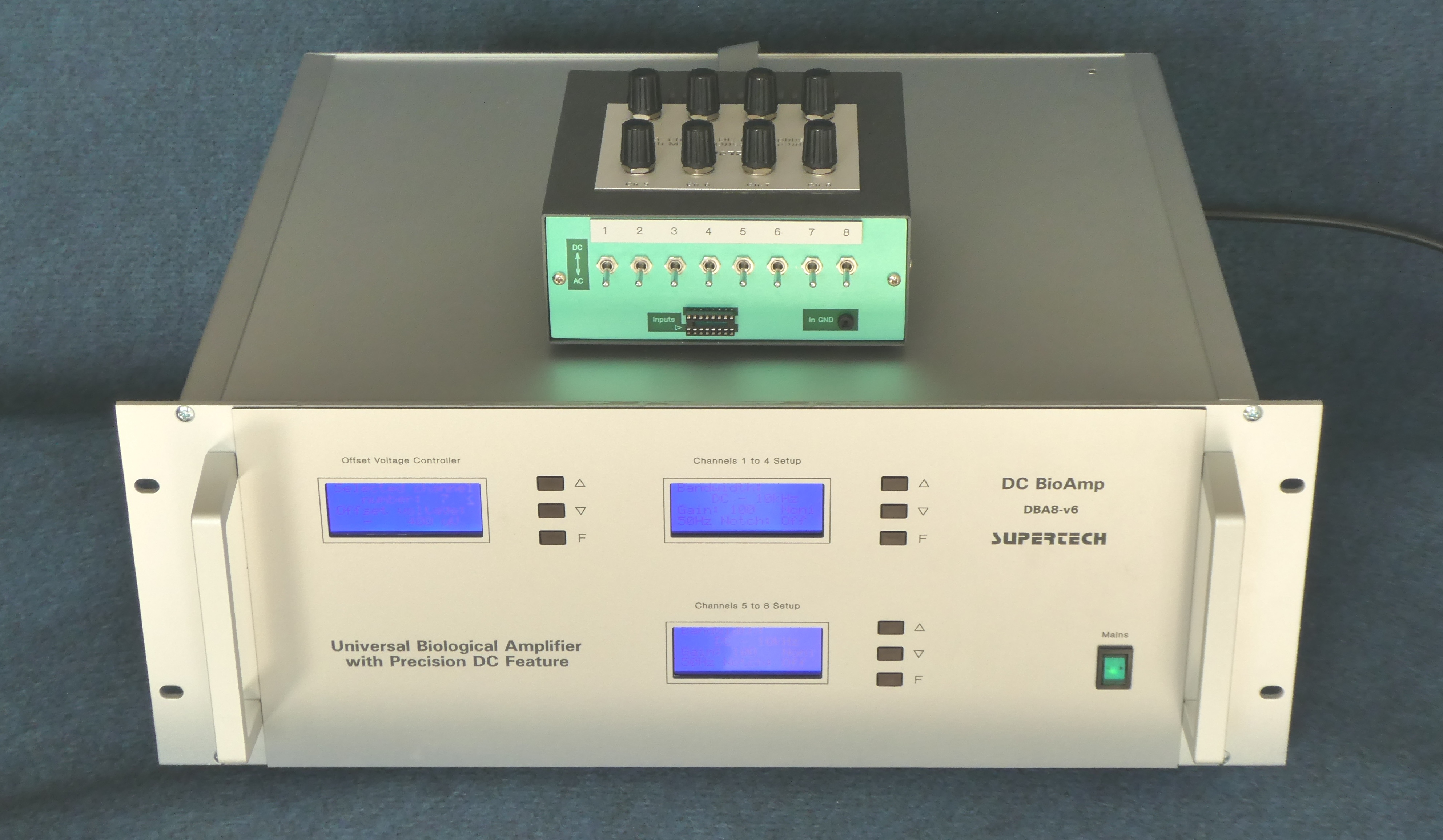 ... with its preamplifier
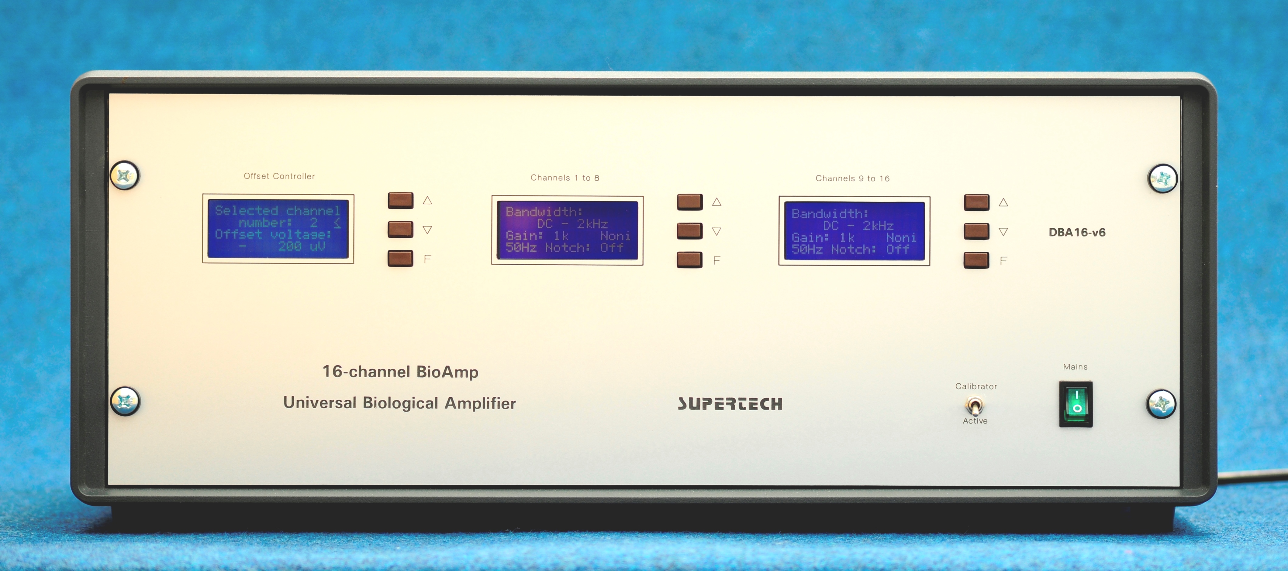 16-channel model
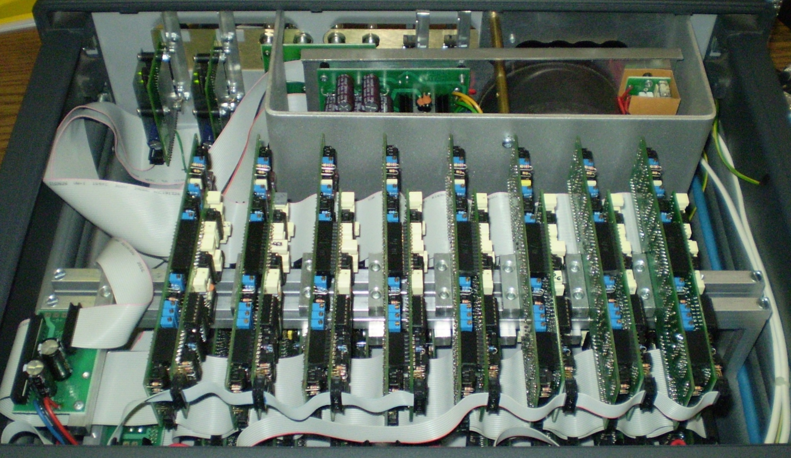 ... its internal looking, the PCBs of channels 1 to 8
Specifications / Technical Data
In the BioAmp system there are 8 positions of gain, 8 positions of high pass filter and 8 position of low pass filter in the menu to choose from. The actual values, what should be realized during the manufacturing process can be ordered with the default parameters, but they can be requested with special values, to meet any special requirements, as well. The default values for the filter and gain sections are listed below. Any combination of the parameters can be selected, even the invalid settings (for instance if the high pass filter is set to higher frequency, than the low pass filter). The invalid settings result no faults in the equipment, only the output voltage will be driven to zero.
| High Pass Filter | Low Pass Filter | Gain |
| DC (0 Hz) | 15 Hz | 500 |
| 0.16 Hz (1 s) | 30 Hz | 1,000 |
| 0.53 Hz (0.3 s) | 70 Hz | 2,000 |
| 1.6 Hz (0.1 s) | 150 Hz | 5,000 |
| 5.3 Hz (0.03 s) | 500 Hz | 10,000 |
| 10 Hz | 2 kHz | 20,000 |
| 30 Hz | 5 kHz | 50,000 |
| 100 Hz | 10 kHz | 100,000 |
There is a possibility to select the full amplifier chain of BioAmp as Inverting or Noninverting characteristics. This selection is also a menu point of the firmware running on the Amplifier Setup Controller.
Offset voltage arisen on the recording electrodes can be corrected on different ways, depending on the actual amplifier model. All the below mentioned voltages are referring to the input of the preamplifier (in other words referring to the electrode).
• Analog offset voltage correction in the Preamplifier:
Offset voltage correction range: +/- 700 mV
Control method: 270 degree miniature or 10-turn helical potentiometers
• Digital offset voltage correction in the Main Amplifier:
Offset voltage correction range: +/- 200 mV
Resolution: 100 µV
Control method: Digital Offset Voltage Controller unit
• The above two methods combined together:
Coarse offset voltage correction in the preamplifier, and
Fine digital offset voltage correction in the Main Amplifier
We manufacture the preamplifiers in two versions: with or without coarse manual offset correction. The version we make for you depends on your decision. The purpose of the manual offset correction in the preamplifier is the canceling of the unwanted DC potential appearing on the tip of the electrode. The offset correction option built into the preamplifier has a wide, +/- 700 mV range, but the potentiometers are not scaled. This voltage correction range is wide enough to eliminate the parasitic DC voltage even of the worst electrode. If your usual electrode have no big offset error, then the manual offset correction option is not necessary, resulting a much smaller preamplifier.
We offer another offset correction possibility, too. It is the Digital Offset Voltage Controller module. It can not be used to compensate the tip potential of the electrode. If you require this unit, it will be a part of the main amplifier. Its offset voltage correction range (referring to the electrode) is +/- 200 mV with a resolution of 100 µV. This offset correction range is not enough to compensate an electrode with great offset error. Even, the Digital Offset Voltage Controller is principally unable to compensate the electrode tip potential, because this unit is located in the main amplifier, several amplifier stages later than the very first stage. The purpose of the Digital Offset Voltage Controller module is to measure the physiological, slow DC potential changes at the electrode on the way by compensating them to zero. If the exact measurement of the functional changes of DC potential is not a requirement, we suggest you not to order the Digital Offset Voltage Controller, because its usage is time consuming and slightly uncomfortable.
Noise
The noise level of BioAmp was measured under the following conditions. A monopolar (single-ended) headstage was used. The input signal of the headstage was generated by a battery-powered square wave generator. The output impedance of this generator was 470 Ohms. The measured noise voltages were referring to the input of the headstage (in other words, they were measured at the output, but they were calculated to the input, divided by the actual gain). The actual settings of the BioAmp Main Amplifier, except the low pass filter, have negligible effect for the total noise characteristics. The noise level depends mainly on the type of the preamplifier and the low pass filter setting. The results of the noise measurement are:
• If the bandwidth is 10 kHz (the low pass filter is opened to the widest range), the input noise RMS voltage is less than 12 µV (50 µV peak-to-peak).
• If the bandwidth is limited to 2 kHz with the low pass filter, the input noise RMS voltage is less than 4 µV (20 µV peak-to-peak).
• If the bandwidth is limited to 500 Hz with the low pass filter, the input noise RMS voltage is less than 2 µV (10 µV peak-to-peak).
The difference between amplifier models mostly depends on the quality of the design. Such features as hum noise, square wave transient response, phase response, frequency domain characteristics, ability of parasite oscillations, thermal stability, reliability, etc. are responsibility of the designer. But there is no real difference in the signal to noise ratios of biological amplifiers manufactured by different firms. The signal to noise ratio depends on the internal design of the amplifier integrated circuits. The race of the smaller electronic noise is a race of the semiconductor manufacturers. The designer can choose the best amplifier ICs of the leader semiconductor factories.
Ground Topology
There is a general design method in the high gain amplifiers, what is applied in BioAmp, as well. Usually in the biological amplifiers, as in our amplifiers, too (if optical isolators are not used) the Input GND and Output GND points are connected together internally. The resistance between them is less than 0.05 Ohms. However they are signed as different points, because in the interior of the amplifier the ground network forms a linear topology, not a single-point GND (as it is advised in the text-books). The suppression of the hum noise is better if the ground line follows the signal line linearly according to the increasing signal amplitudes from the input to the output. To establish a single-point shielding ground is a good solution at the output end of the signal ground line. Unfortunately the security ground wires are also connected to the metal enclosures of the equipments. The security ground wires are usually hum noise sources for the biological amplifiers (because they usually drive some mains-frequency fault currents from other equipments, from other rooms), but they must not be disconnected, they are compulsory to be used. If you use a mains isolation transformer with symmetrical secondary coil, you can eliminate the disadvantage of the security ground (if in your lab it is allowed to use, please check the local rules). The vibration isolation table, the manipulators, the Faraday-cage, metal parts in the Faraday-cage, the oscilloscope, the PC, the Output GND of the amplifier and the real, separated signal ground line (coming from the earth directly, if it is available) should be connected to this single-point shielding ground. But the ground point of the biological target (the slice chamber or the body of the animal) should be isolated from the shielding ground point (special care should be taken with the metal parts close to the target in the Faraday-cage). The Input GND point of the amplifier is used to provide a low impedance ground to the biological object only. The Input GND point to the biological object is the GND pin at the input of the headstage.
The BioAmp system must not be used in human experiments, because it has no European permission for human applications.
The complete User Manual of the BioAmp amplifier system is available for download.
The Downloadable pin assignment of the 20-pin, 2.54 mm output wire connector of each 8-channel output sections of the BioAmp amplifier is available.
Digital Offset Voltage Controller DOVC-16
This unit is an orderable option of the BioAmp DC amplifier models. It is a dedicated microcontroller-based electronic circuit with its own LCD display, built on the front plate of the Main Amplifier.
Specifications / Technical Data
• Number of channels: maximum 16 (it can be used in amplifier models of 1 to 16 channels)
• Offset voltage correction range (referring to the electrode): +/- 200 mV
• Resolution: 100 µV
Preamplifiers (in other words Headstages)
Preamplifiers are built into separated small cases, because they should be located close to the biological target in the shielded environment. The enclosures of the preamplifiers are always made of metal to provide a good shielding of the sensitive input circuitry.
The actual choice of the preamplifiers and headstages (very small preamplifiers) manufactured by Supertech Instruments is quite big. All of them can be built with monopolar (single-ended) inputs or differential (instrumentational) inputs. The available possibilities are:
• Monopolar (single-ended) preamp choice: 1 - 16 channels
• Differential ((instrumentational) preamp choice: 1 - 16 channels
• EEG cable-end version preamp choice: 2 - 24 channels
• If you want to connect our preamp to the main amplifier of another manufacturer, we can build it with the required output connector
Until now we have developed many different preamplifier versions for the BioAmp system, including special preamplifiers for user demands. If you can not find the appropriate model for your special task in our actual choice, we will develop a preamplifier especially for you. Our method is, how we improve the features of our BioAmp system, that we collect all the notices, feedbacks and ideas of our customers and we implement their (may be your) knowledge into the features of BioAmp.
The crucial features of the amplifier ICs, what are continuously developed by the semiconductor manufacturers are: noise (signal to noise ratio), offset voltage, offset drift (thermal stability), input bias current, transient response, bandwidth (slew rate). The topologies of the electronic amplifier circuits are similar at the different amplifier manufacturers. The quality of an amplifier is mostly defined by the quality of the first stages. There are no big tricks in the circuitry. The differences of the amplifiers are basically coming from the parameters of the different IC models used in the preamplifiers. Our engineers make huge efforts to study, measure and compare the newest ICs of different semiconductor manufacturers. Supertech Instruments changes the IC models used in the preamplifiers if a better IC model appears on the market. This way we can keep our electronic circuits the best and up-to-date, because always the most sophisticated ICs are implemented in our constructions.
In our product choice there are DC and AC preamplifiers. The traditional way - described in the textbooks - how to design an AC amplifier is to place capacitors in series into the signal path. This method works in most cases, but specifically in the biological amplifiers it results long "blackout" periods after spike transients. We employ a tricky circuit topology to keep the baseline by the nominal time constant even in the presence of huge disturbances. The signal path is a true DC amplifier in our AC preamplifiers, too.
Specifications / Technical Data
We offer the opportunity for our customers to choose the parameters of the preamplifiers freely, optimized for the given task. You can select one of the listed items for every parameter. The choices are:
• Gain:
10
100
• Input Impedance:
1 MOhm
10 MOhm
Infinite (approximately 1 TOhm)
Any value in the range of 1 kOhm to 10 MOhm
• High Pass Filter:
1 ms (160 Hz)
0.1 sec (1.6 Hz)
1 sec (0.16 Hz)
2 sec (0.08 Hz)
4 sec (0.04 Hz)
DC ( 0 Hz)
• Fixed (non-changeable) parameters:
Bandwidth (upper frequency limit): 20 kHz
Supply voltage: +/- 8 V to +/- 12 V (symmetrical)
Power consumption: 10 mA / channel
BioAmp Main Amplifiers have got universal, multi-purpose connectors for external preamplifiers. This method gives an opportunity to support all the future (yet unknown) preamplifier development projects.
Picture Gallery of a Few Different Preamplifiers
Click on the picture to get it in full size
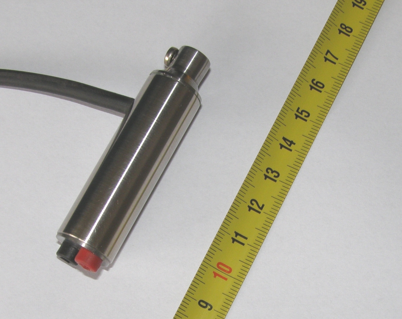 Single-channel monopolar preamplifier (moveable by micromanipulator)
 4-channel monopolar
 4-channel differential
 ... together
 8-channel DC preamplifier top looking
 ... and its front looking
 16-channel custom designed preamplifier prototype
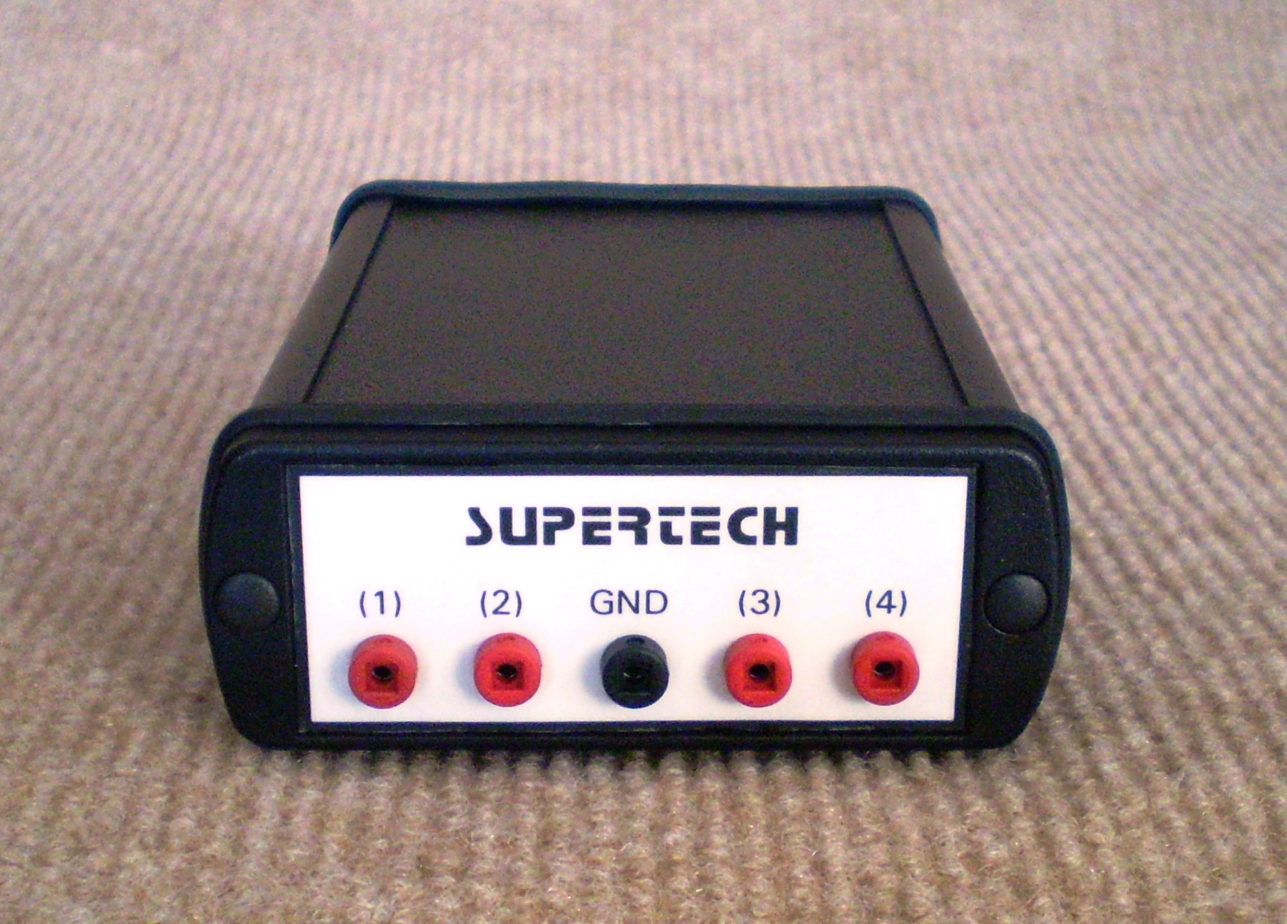
Accessories for Microelectrode Amplifiers
Mains Isolation Transformer TRA-3 with symmetrical secondary coils can efficiently reduce the hum noise level of the amplifiers supplied from such transformers. In our product choice there is a 1 kVA toroidal isolation transformer. It is built in a strong aluminum enclosure with many mains sockets on it. It has got a built-in residual current device and soft start circuit.
Unit Spike Detector USD-1 (Action Potential Level Discriminator) seems to be an old fashioned circuit, but it is very useful in some cases. It can substitute a difficult and expensive data analysis hardware and software systems in such applications where only the distribution of the action potential spikes should be processed.
Special and Unique Amplifiers for Biology
On the one hand our BioAmp amplifiers are extremely versatile biological amplifiers. They can manage every signal recording task in the life science. On the other hand our design engineers have several decades of experience in the field of amplifier design for biology. We have developed many unique amplifiers, not only the universal BioAmp amplifier system. These facts ensure, that we can solve any special amplifier development task in biology and physiology. If you have any special request, please do not hesitate to contact us. We will provide a perfect solution quickly on a very reasonable price. The IonAmp amplifiers are good examples. Originally their prototypes were developed for a unique request. Then, during design procedures of several versions of IonAmp we decided to introduce them as standard products.
Prices
You can find the general warranty and shipping conditions in the beginning of the Services page.
The prices of the different multi-channel BioAmp equipments are calculated according to the following algorithm. If the number of the channels in the system is increased according to the powers of 2, the price concerning one channel (the total price divided by the number of the channels) is always reduced by 16 %.
1-channel universal BioAmp main amplifier UBA1-v7: 1200 EUR (1200 EUR / channel)
2-channel universal BioAmp main amplifier UBA2-v7: 2016 EUR (1008 EUR / channel)
4-channel universal BioAmp main amplifier UBA4-v7: 3384 EUR (846 EUR / channel)
8-channel universal BioAmp main amplifier UBA8-v7: 5680 EUR (710 EUR / channel)
16-channel universal BioAmp main amplifier UBA16-v7: 9536 EUR (596 EUR / channel)
Digital Offset Voltage Controller DOVC-16, 16-channel version, built into any UBAx-v7 amplifier model (turning it to became a DBAx-v7 model): 324 EUR
Digital Offset Voltage Controller DOVC-16, 16-channel version, built-in unit: FREE if the number of channels is 4 or more.
The first set of the simplest, Monopolar (single-ended) headstage HS-x in the same channel number as the main amplifier, without offset voltage correction circuits: FREE if the number of channels is 4 or more.
Monopolar (single-ended) preamp for BioAmp in small metal box, without offset voltage correction circuit:
1-channel Monopolar preamp HS-1: 115 EUR (115 EUR / channel)
2-channel Monopolar preamp HS-2: 194 EUR (97 EUR / channel)
4-channel Monopolar preamp HS-4: 328 EUR (82 EUR / channel)
8-channel Monopolar preamp HS-8: 544 EUR (68 EUR / channel)
16-channel Monopolar preamp HS-16: 928 EUR (58 EUR / channel)
Monopolar (single-ended) preamp for BioAmp, with built-in manual offset voltage correction circuit for every channel:
1-channel Monopolar preamp HS-1-M with manual offset correction: 230 EUR (230 EUR / channel)
2-channel Monopolar preamp HS-2-M with manual offset correction: 386 EUR (193 EUR / channel)
4-channel Monopolar preamp HS-4-M with manual offset correction: 648 EUR (162 EUR / channel)
8-channel Monopolar preamp HS-8-M with manual offset correction: 1096 EUR (137 EUR / channel)
16-channel Monopolar preamp HS-16-M with manual offset correction: 1840 EUR (115 EUR / channel)
Differential (instrumentation) preamp for BioAmp in small metal box, without offset voltage correction circuit:
1-channel Differential preamp HS-1D: 146 EUR (146 EUR / channel)
2-channel Differential preamp HS-2D: 244 EUR (122 EUR / channel)
4-channel Differential preamp HS-4D: 412 EUR (103 EUR / channel)
8-channel Differential preamp HS-8D: 688 EUR (86 EUR / channel)
16-channel Differential preamp HS-16D: 1168 EUR (73 EUR / channel)
Differential (instrumentation) preamp for BioAmp, with built-in manual offset voltage correction circuit for every channel:
1-channel Differential preamp HS-1D-M: 293 EUR (293 EUR / channel)
2-channel Differential preamp HS-2D-M: 492 EUR (246 EUR / channel)
4-channel Differential preamp HS-4D-M: 824 EUR (206 EUR / channel)
8-channel Differential preamp HS-8D-M: 1392 EUR (174 EUR / channel)
16-channel Differential preamp HS-16D-M: 2320 EUR (145 EUR / channel)
1-channel tiny preamplifier (headstage) in cylindrical enclosure without offset voltage correction circuit. It is able to be moved by micromanipulator:
1-channel Monopolar headstage HSC-M for BioAmp in small stainless steel enclosure: 228 EUR
1-channel Differential headstage HSC-D for BioAmp in small stainless steel enclosure: 276 EUR
Intracellular preamplifier HSIC-1 for single-channel BioAmp: 636 EUR
Mains Isolation Transformer TRA-3 (1 kVA, symmetrical secondary coil, in aluminum enclosure, with RCD and soft start): 1128 EUR
Unit Spike Detector USD-1 (Action Potential Level Discriminator): 768 EUR
![]()
![]()
![]()
![]()
![]()
![]()
![]()
![]()
Copyright @ Supertech Instruments - since 1991